 What Can We Expect from a 2-Element Beam?
One poorly appreciated fact about shortened Yagis is to what degree the antenna geometry plays a role in optimizing performance. When looking at shortened Yagis with hatted elements, we found a set of dimensions for the driven element and the reflector which provided close to the best obtainable performance for a 2-element beam designed to maximize front-to-back ratio and to resonate the beam. Interestingly, if we retain a driven element that is about 70% full size, we may use virtually the same main element dimensions with all forms of loading and achieve close to the best performance obtainable.
Because maximum gain at the design center frequency results in poor, if not unusable, performance below the center frequency, the models we shall examine will by optimized for maximum front-to-back ratio and resonance. For some models, the maximum gain frequency will lie very close to (and below) the front-to-back peak frequency, and the beam reversal point for a few samples will fall inside the 2 MHz 10-meter span we have chosen as our test bed. In fact, for loaded Yagis, the performance below the center frequency drops off much more rapidly than performance above the center frequency, especially when compared to the rates of degradation for a full size beam.
We may begin with 3 models: 1 each of the center inductor, mid-element inductors, and linear loaded variety. Each antenna will be spaced 0.12 wavelength (4.1' at 29 MHz). The elements will be close to 70% of full size. The driven element will be 11.48' long, with a reflector 11.95' long. Elements, as in all the models in this refresher, will be 3/8" diameter aluminum.
The center-inductor loaded model called for an inductive reactance for each element of 288 Ohms. This translates into a solenoid with an inductance of 1.5806 uH to achieve resonance and very close to peak front-to-back ratio.
The mid-element loading coils that we needed to yield the same result had 281 Ohms reactance or an inductance for each of the 4 coils of 1.5422 uH. Fig. 1 shows the outlines of the two types of inductively loaded Yagis.

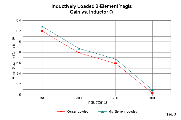
Table 1.  Modeled performance of inductively loaded 2-element Yagis

Antenna   Resistance     Gain (dBi)     F-B (dB)  Feed Z (R +/- jX)

Full-size       --       6.25           11.20     32.14 - j0.00

Center-load
Infinite Q       0       6.20           20.04     17.07 - j0.00
Q=300          0.96      5.79           18.31     18.14 - j0.68
Q=200          1.44      5.59           17.57     18.67 - j1.00
Q=100          2.88      5.03           15.71     20.28 - j1.92

Mid-element-load
Infinite Q       0       6.29           16.84     24.14 + j0.41
Q=300          0.93      5.87           15.66     25.76 - j0.53
Q=200          1.40      5.67           15.14     26.58 - j0.98
Q=100          2.80      5.09           13.75     29.03 - j2.30
Table 1 lists the gain, front-to-back ratio, and feedpoint impedance of these two initial antennas. The table also shows a series load resistance that is necessary to produce coil Qs of 300, 200, and 100, in order to investigate the effects of Q on performance. Models are in free space for this initial design test. The table includes a full-size Yagi of the same (0.12 wavelength) spacing for comparison.
Let's first look at the patterns, shown in Fig. 2. Each patterns set includes the full size Yagi for comparisom. The other plots shows (for effective contrast) the patterns for an infinite Q and a low Q of 100. In both cases, the patterns show that loaded elements often do better at improving the front-to-back ratio at the design frequency than they do with respect to gain. Only with infinite Q does the loaded Yagi gain equal the full size Yagi gain. But, of course, all loading inductors have a finite Q.

Gain: Once we introduce a finite Q, the gain drops rapidly, as is evident if Fig. 3, which tracks the gain over the levels of Q in Table 1. Note that the X-axis is not a linear scale. With an optimistic Q of 300, the gain of either load model approaches a half dB less than a full size Yagi with the same design goals. Another 3/4 dB disappears in the transition from a Q of 300 to a Q of 100. Most coils cited in commercial designs have had values below 300 and above 100, so the actual gain of such antennas will be between 5 and 5.75 dBi (or around 3 to 3.5 dB better than a dipole in free space). Gain expectations for a beam 70% full size and spaced 0.12 wavelength that are higher than this value are unwarranted.
Front-to-back ratio: Shortened Yagis are capable of much higher front-to-back ratios than full size 2-element Yagis, as is clear in Fig. 2. As shown in Fig. 4, the front-to-back ratio does decrease as the Q decreases. The center-loaded model has a theoretic 3 dB advantage over the mid-element model, although that advantage begins to evaporate with finite Qs. Nonetheless, one true advantage of a loaded Yagi over a full-size model is the superior front-to-back ratio.

Feedpoint impedance: Fig. 5 tracks the feedpoint resistance for both forms of loading as we change the load Q. The resistance increases in step with the series resistance of the loading inductors. The center-loaded model exhibits the lowest feedpoint impedance of any of the loaded 2-element Yagis. Although it can be used with coax and a beta match, the low impedance raises questions of basic efficiency in terms of power consumed by resistive losses throughout any practical assembly. Note that as Q decreases, the feedpoint impedance increases proportionally to the total series resistance in the driven element.

It is also significant to examine the operating bandwidth of loaded 2-element Yagis. We would expect something narrower than a full-size Yagi, and figures do not disappoint us. Models for obtaining operating bandwidth and other figures across a span of frequencies must enter the resistance and inductance of the loading coils (rather than resistance and reactance) and allow NEC to calculate the reactances for each frequency selected. Again, the full-size Yagi is presented in Fig. 6 and in Table 2 for comparison with only the Q=200 models of loaded Yagis. (The use of a Q of 200 corresponds closely to the Qs of coils used in trapped and loaded commercial beams.)

Table 2.  A comparison of SWR values relative to driver resonance
Note:  All antennas spaced 0.12 wavelength

Antenna   SWR at    28        28.5      29        29.5      30   MHz
Full-size            7.34     2.37      1.00      1.82      2.78
Center-ld, Q=200    22.85     8.96      1.11      2.45      4.12
Mid-el-ld, Q=200    21.90     8.77      1.12      2.71      4.75
The operating bandwidth of the loaded Yagis is so narrow that the 2 MHz spread is too wide to be informative. It is clear that the SWR climbs very much more slowly above the design center frequency than below it. Whether the antenna has worthwhile characteristics in that region requires that we look at most of the antenna's properties over a narrower spread of frequencies--perhaps a half MHz either side of center. Therefore, Table 3 provides data for 28.5 to 29.5 MHz in 0.25-MHz increments.
Table 3.  Detailed performance from 28.5 to 29.5 MHz

Frequency      28.5      28.75     29        29.25     29.5 MHz

Full size Yagi
Gain (dBi)     6.74      6.49      6.25      6.02      5.82
F-B (dB)       9.79      10.91     11.20     10.41     10.37
SWR            2.37      1.48      1.00      1.39      1.82

Center-loaded Yagi, Q=200
Gain (dBi)     4.87      5.92      5.61      5.08      4.64
F-B (dB)       2.24      9.90     17.63     13.16      9.69
SWR            8.96      2.70      1.11      1.75      2.45

Mid-element-loaded Yagi, Q=200
Gain (dBi)     4.86      5.93      5.67      5.17      4.74
F-B (dB)       1.98      9.01     15.14     12.74      9.75
SWR            8.77      2.70      1.12      1.85      2.71
If the design center frequency is shifted downward by about 150 kHz, the full size Yagi would provide a 2:1 SWR operating bandwidth over the full 1 MHz spread. Gain and front-to-back ratio would be respectable throughout the range (for an antenna of this type).
The operating bandwidth for the loaded Yagis is less than 700 kHz. The maximum gain frequency occurs within this spread and marks the limit of the lower frequency excursion for a 2:1 SWR. Above the design center frequency, the SWR climbs at half the rate as below it. Gain and front-to-back ratio fall off much more rapidly than with a full size model. Fig. 7 shows the gain from 28 to 30 MHz for the 3 antennas using an increment of 0.1-MHz to reveal the finer detail. Note the gain dip at or very near to 28.4 MHz, indicating the frequency at which the forward pattern reverses direction. The reversal point for the full-size Yagi occurs below the limit of the sweep.

Indeed, the higher front-to-back ratio obtainable with shortened and loaded elements now shows itself for what it is: a fairly narrow peak with extended values closer to those of the full size antenna. At the upper frequency limit, gain is less than 3 dB better than a dipole. Fig 8 gives us a wider view that once more shows the pattern-reversal frequency to be near to 28.4 MHz.

The performance of the two inductively loaded Yagis parallels to a very high degree the performance of the full-size Yagi as we vary the height of the antenna above average ground. Table 4 provides data from 0.0625 wavelength to 1.0 wavelength above ground for the loaded Yagis with indortor Q values of 200--with the full-size Yagi for comparison. The table lists only one column for the elevation angle of maximum radiation, since that value is the same within +/-1 degrees at the very low heights and is exactly the same above a height of 3/8 wavelength.

Fig. 9 provides some insight into the variations of gain and front-to-back ratio for the antennas by overlaying elevation and azimuth patterns at heights of 7/16, 11/16, and 1 wavelength. The elevation patterns show the deacreasing elevation angle of the main lobe as the hight increases, along with the development of higher angle lobes. As well, note the varying strength of the rearward lobe in the elevation patterns.

The azimuth paterns show the growth of forward gain with increasing antenna height. However, a more significant feature is the evolution of the rearward lobe or lobes as the height varies. Although these patterns derive from the center-loaded model, they also apply with only very small modification to the mid-element-loadedc and the full-size Yagis.

In general, the overlapping gain lines for the two inductively loaded Yagis track very well with the gain of the full-sixe Yagi, as is evident in Fig. 10. However, both loaded Yagis show greater sensitivity than the full size Yagi in the height region around 7/8 wavelength. Note the visible decrease in gain (that is nonetheless operationally insignificant) in that height region.
The front-to-back curves are more distinct for the three antennas, as shoen in Fig. 11. At the design frequency, 29 MHz, the full-size Yagi shows the lowest front-to-back ratio. However, the full-size antenna curve is also the shallowest in terms of its peaks and valleys. In contrast, the difference between a peak value and the adjacent low value is considerably greater for the loaded Yagis.

In the preceding episode, we determined the recording gain values in dBd could be both misleading and a source of mischief. Simply subtracting 2.15 from the gain in dBi is a fairly useless exercise. Comparing the antenna gain over ground with a dipole at thje same height yields curve of dubious utility. Therefore, these exercises have omitted that data. However, the dipole information is available in past episodes for anyone who wishes to perform the simple calculations.
Between the two types of inductively loaded Yagis, the center-loaded model yields higher peak front-to-back ratios, while the mid-element-loaded model has higher feedpoint impedances for lower losses for loss sources other than the loading coils. The final decision on which type of loaded Yagi to build is an individual option that may depend upon construction and matching variables as well as basic performance. Both loaded Yagis use elements that are 70% of full size, which is about the recommend limit to shortening. If the element lengths decrease any further, the gain would fall rapidly as a function of both the short elements and the higher losses in practical loading inductors. As well, the operating bandwidth would also decrease, limiting the utility of the antenna on all but the smallest amateur bands (such as 30m 17, and 12 meters).
I have purposely excluded the linear-loaded 2-element Yagi of 70% full size from the comparison so far because it has some interesting properties. Linear-loading, especially when executed using loading elements the same size as the main element, is inherently high Q, with all the advantages and disadvantages. Let's scan one of the linear-loaded models, choosing the one with load lines equidistant form the main element by 3" and 3" apart. With the 3/8" diameter aluminum elements 11.48' and 11.95' for the driven element and reflector, respectively, the load lines were 2.37' either side of center (4.75' overall) for resonance and maximum front-to-back ratio. Because the linear-loading elements are directly modeled as physical entities, there are no mathematical loads in the model. Fig. 12 provides the general outline of the beam.

If we use the restristed passband (28.5 to 29.5 MHz) that we used for the inductively loaded beams, we can sample the performance of the antenna at 0.25-MHz intervals. See Table 5.
Table 5.  Performance of a 70% linear-loaded Yagi from 28.5 to 29.5 MHz

Frequency        28.5           28.75          29             29.25          29.5 MHz
Gain (dB         4.78           6.26           5.95           5.15           4.50
F-B (dB)         0.86           6.05           16.31          16.81          11.19
R +/- jX         6.36-j34.83    8.08-j16.56    14.54+j0.03    22.35+j12.14   28.35+j21.34
SWR              15.82          4.47           1.00           2.14           3.27
The SWR-based operating bandwidth for this high-Q model is under 400 kHz at 29 MHz (and proportionately less for lower band models). Peak values are comparable to those obtainable from inductor-loading, but very short-lived as one changes frequency. In fact, within even this restricted passband, the pattern revesal occurs, as indicated by the dips in both the forward gain and the front-to-back values, shown in Fig. 13.

The graph uses a sweept increment of 0.1-MHz, and the lowest values occur at 28.5 MHz. However, the reversal occurs slightly above this frequency, but below 28.6 MHz. To illustrate how sudden and complete the pattern reversal is below the frequency of maximum gain, Fig. 14 shows free-space patterns for the linear loaded Yagi at half-MHz intervals.

Although the front-to-back ratio at 28.5 MHz is negligible, the forward lobe has definitely change direction. with its ingerently high-Q linear loading system, the sample Yagi is useful only over a very narrow bandwidth. Indeed, for most purposes, the lower Q of the sample inductively-loaded versions may be more useful. Nevertheless, they do not have very wide bandwidths, just slightly larger spreads than the linear-loaded version.
Table 6 presents the results of this design experiment. A full-size version of the antenna appears as a comparator for the 3 loaded Yagis.
Table 6.  Performance of full-size and loaded Yagis with 0.16 wavelength spacing

Frequency      28.5         28.75        29           29.25        29.5 MHz
Full size Yagi
Gain (dBi)     6.56         6.34         6.12         5.92         5.74
F-B (dB)       9.79         10.60        10.84        10.68        10.29
R +/- jX       36.9-j19.8   41.9-j9.5    46.9-j0.0    51.5+j9.1    55.8+j17.9
SWR            1.70         1.27         1.00         1.22         1.47

Center-loaded Yagi, Q=200
Gain (dBi)     6.29         6.15         5.75         5.34         4.98
F-B (dB)       6.78         11.35        13.98        12.86        10.87
R +/- jX       13.5-19      17.9-9       22.4-1       26.0+5       28.7+11
SWR            3.12         1.66         1.06         1.28         1.62

Mid-element-loaded Yagi, Q=200
Gain (dBi)     6.17         6.11         5.72         5.32         4.97
F-B (dB)       6.97         13.05        15.84        13.12        10.62
R +/- jX       14.3-30      20.5-14      27.7-.4      34.1+10      39.4+20
SWR            4.51         1.89         1.02         1.50         2.02

Linear-loaded Yagi
Gain (dBi)     6.62         6.59         5.91         5.28         4.79
F-B (dB)       4.30         10.84        14.87        11.95        9.26
R +/- jX       9.3-22       14.3-9       20.1+.4      24.3+8       26.9+15
SWR            4.96         1.85         1.02         1.49         2.08
At a spacing of 0.16 wavelength, a full-size 2-element Yagi is a good match (with a 1:1 balun or choke) for 50-ohm coaxial cable. The other beams require a beta match (or similar). However, note the table carefully: the center-loaded models--both inductor and linear--improved their operating bandwidths and increased their feedpoint impedances by a greater amount than the mid-element-loaded model. At the closer (0.12 wavelength) spacing, the center and mid-element inductor loaded models were very similar in operating bandwidth, with the linear-loaded version much narrower. With the wider (0.16 wavelength) spacing, the mid-element and linear loaded models are on a par with each other (with the linear-loaded model showing a slightly narrower bandwidth), while the center-loaded model shows at least 100 kHz wider operating bandwidth.
At the same time, the wider mid-element-loaded model has lost less of its gain and front-to-back ratio relative to the closer-spaced model than either of the other two antennas. The advantage of one method of loading over another is marginal and may be secondary to structural and other design concerns. The general effect of wider spacing to increase the operating passband of a 2-element Yagi is most effective on the center-loaded models and least effective on the mid-element-loaded model.
Table 7 provides the modeled data for free-space. A linear-loaded model does not appear due to the very large size of the loading transmission-line stubs. In the gain column, R means that the pattern shows gain in the reverse direction. To maximize the potential of these beams, I have raised the inductor Q to 300.
Table 7.  Performance of half-length Yagis using inductive loading with 0.12 wavelength element spacing

Frequency      28.5         28.75        29           29.25        29.5 MHz
Center-loaded Yagi, Q=300
Gain (dBi)     2.06 R       3.73         4.46         3.97         3.46
F-B (dB)       1.09         6.07         27.15        11.07        7.11
R +/- jX       5.5-j27      6.6-j14      12.8-j3      19.2+j2      20.7+j5
SWR            12.7         4.56         1.23         1.52         1.76

Mid-element-loaded Yagi, Q=300
Gain (dBi)     6.32 R       4.16         4.59         4.07         3.57
F-B (dB)       0.98         7.18         31.15        11.04        7.27
R +/- jX       10.6-47      13.4-j24     25.0-j.4     35.3+j6      38.9+j15
SWR            11.1         3.79         1.16         1.50         1.90
At the design frequency, gain has dropped to about 2.5-dB higher than a dipole, and the rate of change is higher than for the 70% models with which we have experimented. However, as elements are radically shortened, it is possible to achieve for very narrow frequency limits indeed exceptional front-to-back ratios with a 2-element Yagi. Of course, the front-to-back ratio quickly diminishes off the design frequency to ordinary levels associated with an antenna with a very narrow operating bandwidth.
Newer operators, especially those whose prior antenna experience has been limited to verticals or simple wire dipoles, often make an error when they use their first beam. Received stations in the forward direction seem to be clearer and stand out above the background noise, whether atmospheric or from other stations. The new beam user tends to assume that the increased signal-to-noise ratio is a function of gain. As a result, many a mediocre beam has enjoyed an unwarranted reputation for its forward gain.
The attribution of clarity to gain is very often an illusion. For very small beams--like the 2-element Yagis with which we have experimented--the improvement in received signals may be largely do the the antenna's front-to-back ratio. More correctly, it is due to the general reduction of gain to the rear quadrants. Even a 10-dB front-to-back ratio tend to indicate an average gain level to the rear that is 15 or more dB lower than in the forward direction. (Remember that for almost all of our designs, the 180-degree front-to-back ratio is also the worst-case front-to-back ratio.) For reception, the front-to-back ratio is as important--and often more important--than forward gain in allowing us to hear well in the favored direction.
The actual forward gain plays its most important role with the transmitted signal. Whether the station on the otheer end can hear us is a joint function of our forward gain and the conditions between us. (In many instances, the outgoing and the incoming conditions may not be the same, and so what we receive may not indicate correctly what is happening in the ionosphere to the signal that we transmit.) Since we lack means to separate and measure the two factors, we tend to over-estimate the gain of our 2-element antenna. The illusion may create a happy feeling, but it is often just an illusion.
There is one more design illusion we can create with this half-size beam. Note that the SWR increases above the design frequency at a slow rate. The antenna is capable, in strictly SWR terms, of an operating bandwidth of over 0.5 MHz. However, in the upper half of the range, gain exceeds a dipole only by about 1.5 dB or so, and the front-to-back ratio is on a constantly descending curve. Citing the design frequency performance figures and then, without further explanation, providing a figure for operating bandwidth, might easily mislead a potential builder with respect to performance anticipation.
It would be interesting to see to what degree the problems associated with half-size 2-element Yagis might be overcome by increasing the spacing. Therefore, let's look at these same antennas re-optimized for front-to-back ratio and resonance with a spacing of 0.16 wavelength (5.4' at 29 MHz). Table 8 supplies the modeling data.
Table 8.  Performance of half-length Yagis using inductive loading with 0.16 wavelength element spacing

Frequency      28.5         28.75        29           29.25        29.5 MHz
Center-loaded Yagi, Q=300
Gain (dBi)     2.75         4.83         4.61         3.92         3.40
F-B (dB)       0.34         8.56         17.16        9.99         7.90
R +/- jX       6.7-j22      9.1-j11      14.2-j3      16.6+j2      17.2+j8
SWR            7.78         2.72         1.22         1.25         1.71

Mid-element-loaded Yagi, Q=300
Gain (dBi)     2.89         4.95         4.78         4.13         3.61
F-B (dB)       0.15         7.78         15.94        10.55        7.40
R +/- jX       13.3-j41     17.7-j19     27.2-j2      33.1+j8      35.3+j20
SWR            7.00         2.50         1.10         1.40         1.96
Interestingly, the wider spaced versions of the half-size Yagi achieve marginally more gain than the closer spaced versions, although the front-to-back ratio peak is much smaller for these Q=300 models. As a reminder, the fact that the SWR does not go to 1.0 is due to the modeling process used: the antennas were resonated with lossless coils and then losses were added to achieve the desired Q.
Clearly, the SWR curve is also flatter for these antennas than for the closer models, and operation over a 600 kHz span of 10 meters should be possible (with proportionately smaller bandwidths on lower bands to which the antennas might be scaled). Although the resistive component of the feedpoint impedance of the center-loaded model is low enough to cause concern, the impedance of the mid-element model is high enough for an efficient beta match to coaxial cable.
As a parting shot, let's place the mid-element-loaded version of the half-size 2-element Yagi, with its 3/8" diameter aluminum elements, over real ground and see what we get. Table 8 tells the story.
Table 8.  Mid-element-loaded Yagi, Q=300, at various heights above average ground
Height    TO Angle    Gain dBi     F-B dB      Feed Z Ohms
FS        --           4.78        15.94       27.23 - j2.46
1/8 wl    58           3.92         5.82       22.13 - j4.73
1/4       45           7.17        11.40       23.94 + j0.08
3/8       34           8.46        17.41       28.24 + j0.36
1/2       26           9.47        19.13       29.74 - j3.01
5/8       21           9.89        14.38       26.65 - j4.49
3/4       18           9.81        13.85       25.69 - j2.09
7/8       16           9.91        16.20       27.41 - j1.13
1         14          10.19        18.14       28.49 - j2.58
Compared to a dipole, the half-size Yagi suffers at low heights (below 3/8 wavelength) due to its high elevation (or take-off) angle of maximum radiation angle. Above that height, it provides a consistent gain over a dipole in the 2.5 dB ballpark. Front-to-back ratio and feedpoint impedance are stable with height increases, making the antenna quite predictable. The one limiting factor in these figures is that they are peak figures. Performance in one or another way will be less as we move off the design frequency.
This and the other models should make usable antennas, especially when scaled for lower frequencies--so long as we do not expect of them or claim for them more than they can do.
A word about the models: although every effort has been made to optimize them in accord with the expressed design goals of maximum front-to-back ratio at antenna resonance, there is no guarantee that another few hundredths or even a tenth of a dB might not be garnered by even more painstaking modeling. However, do not expect NEC or MININEC to yield much more than these models. If a model seems to deliver a lot more than the ones in this refresher, it is likely that the model has a problem or in some way presses one or more of the limits of the modeling program.
Two-element driver-reflector Yagis, in either full-size or shortened versions, have an important place in amateur radio. Understanding what they can and cannot do is critical to station and operation planning. I hope this refresher on 2-element performance contributes something to that cause. However, we have wholly neglected the driver-director 2-element Yagi. Therefore, let's spend one more episode on this type of Yagi and other methods of increasing 2-element Yagi gain.
Updated 05-07-1997; 04-29-2006. © L. B. Cebik, W4RNL. Data may be used for personal purposes, but may not be reproduced for publication in print or any other medium without permission of the author.
![]() Go to Part 5: Strategies for Improving Forward and Rearward Performance
Go to Part 5: Strategies for Improving Forward and Rearward Performance