

The "terminated, tilted folded dipole" (T2FD) antenna has been subject to much recent conversation, some of which has come my way in the form of questions about modeling the antenna. So I decided to take a systematic look at models of the T2FD. The original T2FD was intended for use as a vertical or a sloping antenna, often as an appendage to the tall tower. Leter (WWII), the antenna found use as a horizontal "all-band" wire antenna used in either flat or inverted-V configurations. These notes will deal largely with the vertical and sloping versions. For further and deeper looks into the horizontal versions, see "Notes on the Terminated Wide-Band Folded Dipole".

The two models I investigated are sketched in Fig. 1 (shown horizontally to save space). Both are similar in that they are indeed folded and dipoles, although not folded dipoles in the normal sense of that term. The resistor placed opposite the feedpoint limits the impedance excursions at the feedpoint relative to an unterminated folded dipole. At the same time, the resistor also introduces losses into the antenna in the form of converting some of the RF energy into heat.
Both antenna are designed for use from 2 MHz through 30 MHz as an initial design criteria. We shall explore limitations in that frequency spread along the way. The "Wide-Long" version coincides with standard construction formulations, since the antenna is about 300/F(MHz) long and 10/F(MHz) wide. (Excessively fussy cutting formulas for this antenna are largely superfluous, since strict resonance is not in question.) The "Narrow-Short" version generally approximates or approaches the dimensions of commercial versions of the T2FD, even if that name is not used for the antenna. Both antennas use #12 copper wire.
Modeling the T2FD involves nothing that in any way presses the limitations of NEC (either -2 or -4), so long as the segment length in the long wires is not out of balance with the segment length in the short wires and as long as sufficient segments are used per wavelength for all frequencies to be investigated. In short, nothing in the antenna design suggests that NEC should not give accurate predictions of performance.
We shall look at several questions that seem to perpetually arise in connection with the T2FD. The first involves the antenna's feedpoint impedance across the frequency range of intended use, relative to the selected value of terminating resistor. The second will involve antenna patterns when the antenna is oriented vertically. Related to this second question is the matter of tilting the antenna, as our third inquiry. Finally, we shall look at the question of losses relative to uses to which one might put the T2FD.
Since these are notes on two models of the T2FD, they do not yield more than suggestive results. Hence, nothing in these notes should be construed as fixed, final, or necessarily in rebuttal of existing claims, many of which may be based on different version of the antenna type.
One common recommendation for the T2FD is to use a 390-Ohm resistor for the termination and to employ 300-Ohm feedline. (The general recommendation is to use a terminating resistor that is about 5% to 10% higher in value than the feedline characteristic impedance.) I performed frequency sweeps with this configuration using both models. The technique is to obtain an SWR curve from 2 to 30 MHz using as a standard the characteristic impedance of the desire line, with a resistive load in the model matching the desired terminating resistor.

Fig. 2 shows the results of the 390-300 Ohm combination for the standard T2FD configuration cut for 2 MHz. (The model used is the 165' long wide version from Fig. 1. Although called a 2-MHz antenna, The antenna is about 1.2 wavelength long at 3 MHz.) The SWR excursions are very wide, ranging from about 1.2:1 to nearly 9:1.
I could provide a mass of similar graphics representing my search for a combination of terminating resistor and feedpoint impedance standard that would yield the shallowest SWR excursions. Instead, I shall drop to the bottom line. For the standard "wide" T2FD configuration cut for a lowest frequency of use of 2 MHz, a loading resistor of 850 Ohms combined with a feedpoint impedance standard of 900 Ohms yields the following "best" SWR curve.

In Fig. 3, the highest value of SWR relative to 900 Ohms is about 2.1:1, with peaks in this vicinity occurring every 6 MHz from 4 to 28 MHz. This value does not coincide with any one particular feedpoint impedance, as the following table shows.
Freq.       R +/- jX
 4        1435 - j 615
10        1085 - j 700
16         855 - j 665
22         690 - j 575
28         590 - j 466
Although the reactive component is consistently negative at these frequencies, the resistive component ranges from well above to well below the 900-Ohm standard. The resistive component of the source impedance ranged from 450 to over 1400 Ohms, while the reactive component ranged from +j250 to -j700 Ohms across the frequency span. These ranges must be considered tentative, since the check points are 1 MHz apart.
Interestingly, the narrow version of the T2FD with its shorter length (100') also required an SWR standard of 900 Ohms, with a terminating resistor only 50 Ohms less (that is, 800 Ohms) than that used for the optimized wide T2FD version.

With these conditions, as shown in Fig. 4, one can obtain an SWR curve between 2 and 30 MHz of under 2:1 relative to 900 Ohms. The peak values occur at 10 MHz intervals: 7, 17, and 27 MHz. The wire is about 1.2 wavelength long at 5.5 MHz. However, the extreme resistive and reactive component values are not very different from those of the standard configuration.
In principle, it would seem that some scheme to transform the standard impedance value for both versions of the antenna (900 Ohms) down to a desired feedline value (perhaps a 50-Ohm coaxial cable) might be necessary. For a 50-Ohm result, an 18:1 transformation would be in order, perhaps done in two steps: 9:1 followed by 2:1. However, due to the high values of reactance present at the feedpoint at numerous frequencies within the overall antenna design range, one would need to use great care in selecting the means of impedance transformation. Some methods and materials may combine to yield losses which might then show artificially low values of SWR on the final feedline. These losses would be in addition to those incurred via the terminating resistor. Whether these additional losses would be acceptable might well depend upon the application proposed for the antenna.

Fig. 5 shows the elevation pattern of the standard vertical configuration T2FD (as cut for a 2 MHz lower limit or a length of 165') at 5 MHz. The low angle of radiation is one of the features of the T2FD that make it appealing in certain applications. The antenna remains 20' above average earth at the lower end. Note that the pattern is not symmetrical when taken across the plane of the wires (with a 5' separation), with slightly less gain in the direction of the loaded wire. In general, the closer the wire spacing, the less the gain differential. Broadside to the plane of the wires, the elevation pattern would be symmetrical with a gain intermediate to the high and low values shown in this edgewise view.

In Fig. 6, we find the elevation pattern for the same vertical antenna at 10 MHz. (Note that the wider standard configuration tends to show some pattern displacement to one side or the other, due to the spacing of the wires. The more dominant side depends on the frequency of operation. The narrow version shows an almost perfectly circular pattern.)
The most noteworthy aspect of Fig. 6 is the absence of low angle radiation, with the first main lobe peaking at greater than 30 degrees above the horizon. The high-angle of the main radiation lobes results from the fact that at 10 MHz, the antenna is well over 1.5 wavelengths long. A linear vertical doublet would show a low radiation angle to a length of about 1.25 wavelengths. As the antenna becomes longer, the main lobes are no longer broadside to the wire, but at angles to the wire. This shows up in the vertical configuration as high-angle radiation rather than low-angle radiation that would correspond to a broadside pattern in free space (or when used horizontally)

To establish that Fig. 6 is no fluke, Fig. 7 is the elevation pattern for the antenna at 15 MHz.
The explanation for these less than optimal patterns is the nature of the antenna. Although terminated, the antenna is still a folded doublet and shows in free space all of the pattern tendencies of any dipole. So long as the antenna is 1.25 wl long or less, then there is in free space a single main lobe broadside to the antenna wire. (In the range of 1.1 to 1.35 wl long, the antenna shows the side lobes typical of the extended double Zepp.) The main lobe, when the antenna is vertically oriented over ground, results in a low-angle lobe of radiation or reception sensitivity.
As the antenna length approaches 1.5 wl, the broadside lobes give way to dominant angular lobes relative to the plane of the wire. When the antenna is vertically oriented, these lobes combine to form high angle radiation maxima, with low angle radiation either much reduced or wholly absent.
The standard T2FD at 165' long reaches the 1.25 wl limit at about 7.5 MHz, while the shorter 100' version reaches the same limit at about 12.3 MHz. Beyond 8 MHz for one and 13 MHz for the other, high angle patterns become standard. When any version of a T2FD reaches a length relative to the operating frequency of more than 1.25 MHz, its utility for low angle radiation may become less than desired.
The solution to this problem is fairly simple: the construction of a second T2FD. A T2FD (this time in the narrow configuration) of 40' overall length and 0.25' width, using the same loading resistor and feedpoint standard impedance was modeled. The SWR graph is a single curve that does not reach 2:1 from 7 through 30 MHz when the antenna bottom is 20' above average earth. In fact, the peak value of SWR relative to a 900-Ohm standard is 1.72, which occurs between 19 and 20 MHz. This new antenna is already over 0.5 wl long at 14 MHz and does not reach a length of 1.25 wl until nearly 31 MHz.

Fig. 8 shows the elevation pattern of the second T2FD at 15 MHz, for comparison with the pattern for the long T2FD in Fig. 7. Although the peak gain value is lower with the shorter antenna, the radiation is at an angle of greater utility in most applications.

Fig. 9 shows the two patterns. The vertically oriented T2FD shows minimal pattern displacement from one direction to the other. However, the tilted version shows a heavy pattern displacement, but in neither direction is the radiation field as strong as at the peak of the lowest lobe of the vertical version.
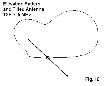
Fig. 10 shows the orientation of the pattern displacement to the tilt of the antenna. The patterns off the sides of the antenna are equal and approach those of the vertically oriented antenna. Nothing in the models shows any advantage to tilting the antenna with respect to skip communications or reception. Perhaps the only advantage may be mechanical, for those lacking a suitable high support from which to hang the antenna vertically.
The losses in the terminating resistor are considerable, ranging from nearly half power to amounts in excess of 90% of the available RF power. The pattern of losses is not a simple smooth curve, but varies throughout the operating range of the antenna. The following graph plots the losses in terms of dB. For reference, a 3 dB power loss represents half the power being dissipated in the resistor. Higher values indicate more of the power being dissipated rather than being radiated (or transferred to the receiver).

Fig. 11 is notable because it tracks the SWR curves for the two versions of the T2FD in quite interesting ways. The lowest losses in the wide or standard version of the T2FD (165' long) occur at the same frequencies as the peaks in SWR. For the shorter (100') version, the lowest loss points show a slight displacement (1 MHz) but occur at the same intervals. The actual loss within the resistor is a function of the current on that segment of the antenna. Other lengths and load resistors will show different levels and patterns of loss from the terminating resistor.
It should not be surprising that the shorter T2FD shows much higher losses at the lowest frequencies of operation, since the antenna is about 0.2 wl long at 2 MHz. Basic antenna efficiency increases rapidly as the antenna length passes the 0.3 wl mark, which is well above 3 MHz for the shorter antenna. Indeed, we may call the frequency at which the antenna is about 1/2 wavelength long the "knee" frequency. Below the knee, gain frops rapidly and losses (as well as dissipation in the terminating resistor) increase with equal rapidity.
The losses incurred in the terminating resistor occur in the form of heat. For reception-only applications, simple low-wattage non-inductive resistors may be used. For transmitting purposes, heat dissipation for the terminating resistor assembly becomes a major factor in antenna design.
There are a number of questions that modeling cannot answer, even if precise design and installation data are supplied. For example, the standard version of the T2FD is said to be quieter than random wires and doublets in receiving applications. The closed loop construction with wider spacing between wires may well account for this report, but modeling cannot itself show the phenomenon.
Nonetheless, the models used here were constructed with sufficient care to warrant reasonable trust in the analytical results. These notes may provide a basis for prospective users to check out their proposed designs prior to installation to ensure that the resulting antenna has a good chance of meeting expectations.
Updated 06-07-1999. 02-17-2007. © L. B. Cebik, W4RNL. Data may be used for personal purposes, but may not be reproduced for publication in print or any other medium without permission of the author.