
 Planar Reflectors
In this series so far, we have examined several types of planar arrays, including a simple dipole driver, a phase-fed dual-dipole driver, and both single and double rectangle drivers. Our goals has been to see how the properties of these driver assemblies vary across a wide range of reflector sizes ranging from 1 to 2 wavelengths per vertical and per horizontal side. All of the NEC-4 models employ a standard wire-grid reflector using 0.1 wavelength segments. As well, all models are designed for a 50-Ohm feedpoint impedance. The test frequency is 299.7925 MHz so that 1 m = 1 wavelength throughout the exercise.
Within the limitations of the modeling techniques involved, we have arrived at a number of tentative conclusions.
1. The feedpoint properties of any driver so far, once established, remain the same regardless of the reflector size.2. The ideal maximum gain height of the reflector is about 1.2 m (wavelength), regardless of the driver vertical or horizontal dimension.
3. The ideal maximum gain reflector is one that extends horizontally beyond the driver system by about 0.5 m to 0.6 m (or wavelength).
4. The rectangular drivers provide simpler array construction, but much narrower 50-Ohm SWR operating passbands than the phase-fed dual dipole driver.
5. So far, the phase-fed dual dipole driver and the double rectangle provide the maximum gain from the array.
6. In none of the arrays does the maximum front-to-back ratio coincide with maximum gain in terms of reflector size. If we use a front-to-rear ratio, averaging the rearward gain across the 180 degrees of rearward directions, it appears that the larger the reflector, the lower the average rearward gain and the higher the front-to-rear ratio.
To the collection of driver assemblies, we should add at least two more entries: the bobtail curtain and the double diamond. Both are adaptations of antennas used in the lower HF range and belong to the general class of SCVs or self-contained vertical antennas. Although the double diamond driver has appeared in at least some articles on UHF utility antennas, the bobtail has--to my knowledge--not seen wide use above the lower HF region.
The Bobtail Curtain and a Planar Reflector
A bobtail curtain consists of three 1/4 wavelength vertical antennas fed in phase. To effect phasing and to complete the 1/4 wavelength sections, horizontal lines about 1/2-wavlength long connect one vertical element to the next. Each half wavelength line acts as a pair of 1/4 wavelength completions for its vertical section and as a phase reversal section (reversing both voltage and current so that the verticals remain in phase with each other). In the lower HF region, where wire versions of the antenna are common, the horizontal lines are elevated, with the verticals hanging downward. This system places the high current region of the vertical sections as high as feasible. When used at VHF and UHF frequencies, the entire antenna is normally many wavelengths above ground. Hence, the placement of the horizontal wires becomes a matter of building choice. For an article in Communications Quarterly some years ago (See The Half-Square on 2 Meters for an earlier version of the article) I constructed parasitic beams using both half-squares and bobtail curtains with the horizontal wires downward.
Although horizontally polarized radiation from the phase-wires is not completely canceled, it is very weak compared to the vertically polarized component. Hence, we may think of both the 2-legged half-square and the 3-legged bobtail curtain as essentially vertical antennas. As a result, they are apt candidates as drivers for a planar reflector. By feeding the junction of the bobtail's center vertical and the phase-wires extending on each side toward the end verticals, we obtain a symmetrical or balanced feed for the end verticals. The required corner feedpoint for a half square does not permit such balance, and therefore, I have by-passed it in favor of the bobtail curtain. When we examined the single and double rectangles, we noted that for optimal performance, a double rectangle would be (for each section) horizontally longer and vertically narrower than the counterpart single rectangle. We find that a similar situation applies to the bobtail curtain relative to the half-square. For the driver assembly used in our model, the vertical legs will be 0.271 m (wavelength) long, while the individual horizontal wires will be 0.45 m (wavelength) long--for a total horizontal length of 0.90 m (wavelength). As shown in Fig. 1, the required spacing from the reflector is 0.185 m (wavelength). As with the rectangles, the wire diameter is 4 mm.

As the sketch shows, I have placed the horizontal lines at the model top. However, in these free-space models, the placement is arbitrary and has no direct bearing on array gain. However, it does have a bearing on certain pattern properties that we shall note before leaving this driver. The following lines show the master model for the bobtail curtain driver, calling up one of the Green's files for a reflector.
CM Bobtail curtain 0.185 m from planar reflector
CE
GF 0 R-H16-V12.WGF
GW 24 5 .185 0 -.136 .185 0 .136 .002
GW 25 8 .185 0 .136 .185 .45 .136 .002
GW 27 5 .185 .45 -.136 .185 .45 .136 .002
GW 28 8 .185 0 .136 .185 -.45 .136 .002
GW 30 5 .185 -.45 -.136 .185 -.45 .136 .002
GE 0 -1 0
EX 0 24 5 0 1 0
RP 0 361 1 1000 -90 0 1.00000 1.00000
RP 0 1 361 1000 90 0 1.00000 1.00000
EN
The 0.185-m spacing of the driver assembly from the reflector stems in part from the fact that by itself, the array shows a feedpoint impedance of about 40 Ohms when fed at the junction of the center vertical with the phasing lines. The resistance and reactance behavior of the array tends to be independent of the reflector size, with the exception--noted for all planar reflector arrays so far--that we find a small drop in resistance and a tilt of the reactance toward the inductive side as we pass through the vertical dimension of the reflector that yields maximum gain for any given horizontal dimension. Likely as a result of the "loose ends" of the bobtail, which are non-symmetrical vertically, we find a slightly larger than normal swing of the 50-Ohm SWR as we pass through all of the 36 reflector sizes used in the survey. SWR values range from 1.01:1 up to 1.09:1 as we change reflector sizes at the test frequency. For most of the driver assemblies that we have explored, a range of 1.01:1 to 1.04:1 is more the norm.
Likewise, beamwidth behavior closely resembles that of the double rectangle in terms of both actual values and changes as we alter the reflector size. The H-plane beamwidth varies between 48 and 52 degrees for the entire set of sample reflector sizes and changes by no more than 2 degrees for any single increment of either the horizontal or the vertical dimension. However, as with the other drivers, the E-plane beamwidth shows a 4-degree decrease as the vertical dimension passes through the length that yield maximum gain. As well, when the reflector vertical dimension passes from 1.4 m (wavelength) to 1.6 m (wavelength), we see a 6-7-degree jump in the E-plane beamwidth, with a more orderly and slower progression of increases for larger vertical dimensions. The total span of E-plane beamwidths runs from about 57 degrees (at maximum gain) to 73 degrees, with the largest figure occurring with the largest vertical dimension, regardless of the horizontal dimension of the reflector.

As shown in Fig. 2, the bobtail curtain driver shows a very orderly set of curves for gain across the set of reflector sizes. As in all of these exercises, the individual graph lines represent increments of the horizontal dimension, while the X-axis shows the increments along the vertical dimension. Maximum gain occurs--consistent with every other driver sampled--with a vertical dimension of 1.2 m (wavelength), regardless of the horizontal dimension. However, overall, the highest free-space forward gain achieved (11.31 dBi) occurs with the largest reflector size sampled. Because the value for the 1.8-m horizontal dimension is so close (11.30 dBi), it is unlikely that the gain rises any higher with reflectors that are longer horizontally. The 0.55-m extension of the reflector beyond the limits of the outer vertical radiators at maximum overall gain is consistent with values obtained for other drivers that we have explored.

Unique among the drivers that we have examined, the bobtail curtain shows 180-degree front-to-back peaks within the limits of vertical dimensions for almost all of the range of horizontal dimensions. Only a horizontal length of 2.0 m places the front-to-back peak definitively outside the range of reflector sizes used. When interpreting the curves, if two adjacent peak values are very nearly the same, you may assume that the actual peak value occurs between them at a higher value than for either value shown. This is true for the horizontal dimensions of 1.2 m and 1.4 m especially.
The gain and the front-to-back curves give the bobtail curtain driver a sense of orderliness that belies an anomaly occasioned by its vertically asymmetrical structure. In fact, the E-plane patterns for the array shows a distinct tilt that ranges from a maximum downward tilt of 7 degrees to a maximum upward tilt of 5 degrees. Maximum downward tilt occurs with the smallest horizontal dimensions. In the mid-range of horizontal dimensions, the tilt swing is between -2 and +4 degrees. As the horizontal dimension reaches its 2.0-m limit, the tilt is most positive as the vertical dimension also reaches its 2.0-m limit.

Fig. 4 illustrates--on the left--the degree of E-plane pattern distortion created by the tilt with a smaller reflector. However, the distortion is minimal in the pattern on the right, which uses the same vertical height, but is nearly twice as wide horizontally. The H-plane patterns for these two cases, shown in Fig. 5, display none of the asymmetry, since the array driver is perfectly symmetrical from one outer vertical to the other one.

To reverse the tilt, one need only move the horizontal phase lines from the model driver top to its bottom. It is unlikely that the tilt would be great enough to allow pattern direction for a particular application. However, for the bobtail driver, one cannot assume a perfectly normal set of elevation patterns over ground. Rather one must accurately model or measure the elevation lobe structure before freezing a design.

The 50-Ohm SWR curve for the bobtail curtain driver with its planar reflector follows the pattern of all of the other drivers in this exercise. One curve stands in for all, since the feedpoint resistance and reactance behaviors change so little as we vary the reflector sizes. The 50-Ohm 2:1 SWR passband extends from about 288 to about 310 MHz, for a 7.3% bandwidth. This value marginally exceeds the values obtained by the rectangles, but is less than 1/3rd the passband values achieved by the dual-dipole driver system.
The unique features of the bobtail curtain driver are three. a. It achieves the highest modeled gain of any of the driver systems. b. It places most of the maximum front-to-back peaks within the range of reflectors sizes used in the exercise. c. It tilts the E-plane patterns slightly, although not enough to detract from its use. Like the other driver systems, it achieves maximum gain with a vertical reflector height of about 1.2 wavelength and with a horizontal reflector width that represents between a 0.5- and 0.6 wavelength extension of the reflector beyond the limit of the driver. As well, the feedpoint impedance behavior is in line with the other drivers.
The Double Diamond Plus a Planar Reflector
Our final driver system is not the last possible candidate for the task. Instead, it is simply the last one that we shall survey. The double diamond is also an SCV, but at lower HF, we usually see it in the form of a double delta. It consists of two diamond-shaped quad loops joined at the hip, that is, joined at a side peak dimension. Fig. 7 shows the outline of the double diamond applied to our planar reflector study.

The model for the double diamond follows construction practice for the antenna. A short vertical wire forms the junction of the individual diamond quads, and we place the feedpoint on that short wire. Essentially, we are feeding two quad loops in phase with each other. We obtain maximum gain from the double diamond when we squash it slightly, as we did for both the bobtail curtain and the rectangles. Hence, the vertical dimension is 0.323 m (wavelength) from peak to peak. However, each diamond is 0.4024 m (wavelength) from peak to center wire, horizontally. Hence, the total horizontal dimension is 0.8046 m (wavelength) from outer peak to outer peak. The following lines show a sample model for the double diamond.
CM Double diamond 0.148 m from planar reflector
CE
GF 0 R-H16-V12.WGF
GW 24 1 .148 0 -.005 .148 0 .005 .002
GW 25 30 .148 -.4024 0 .148 -.2012 .1615 .002
GW 26 30 .148 -.2012 .1615 .148 0 .005 .002
GW 27 30 .148 -.4024 0 .148 -.2012 -.1615 .002
GW 28 30 .148 -.2012 -.1615 .148 0 -.005 .002
GW 29 30 .148 .4024 0 .148 .2012 .1615 .002
GW 30 30 .148 .2012 .1615 .148 0 .005 .002
GW 31 30 .148 .4024 0 .148 .2012 -.1615 .002
GW 32 30 .148 .2012 -.1615 .148 0 -.005 .002
GE 0 -1 0
EX 0 24 1 0 1 0
RP 0 361 1 1000 -90 0 1.00000 1.00000
RP 0 1 361 1000 90 0 1.00000 1.00000
EN
The model uses a spacing of 0.148 m (wavelength) from the driver to the reflector. With the dimensions shown, the test frequency 50-Ohm SWR varies only from 1.00:1 to 1.03:1 across the entire range of reflector sizes used in the study. Resistance behavior is very uniform, with a slight (1 Ohm) dip in value one vertical reflector increment beyond the vertical size yielding maximum gain. The reactance reaches its most capacitive value at the vertical reflector height that corresponds to the maximum gain for any given horizontal dimension. It reaches its most inductive value at a vertical height of 1.8 m. However, the total modeled reactance range is only about 0.8 Ohm.
The beamwidth is equally well-behaved. The E-plane beamwidth range runs from 56 degrees to a maximum of 72 degrees. The lowest value, of course, occurs when the vertical reflector dimension is right for maximum array gain. We find the jump in beamwidth (6 to 8 degrees) in the shift of the vertical reflector dimension from 1.4 m to 1.6 m. The H-plane beamwidth varies over a smaller range--from 52 to 58 degrees across the span of sampled reflector sizes. There is no definitively identifiable peak value, although there is a growth in beamwidth as the vertical reflector dimension increases.

The gain curves for the double diamond form a coherent set, as shown in Fig. 8. The line for the largest horizontal dimension (2.0 m) shows that it is beyond the size to yield maximum overall free-space gain by that fact that it descends more rapidly than the other curves after passing the vertical dimension that yields maximum gain. As we may have grown to expect, the double diamond achieves maximum gain with a vertical reflector dimension of 1.2 m.
The maximum gain achieved by the double diamond (11.13 dBi) is second only to the bobtail curtain. In fact, as a way of reviewing the driver assemblies that we have looked at, we can create a table of maximum free-space gain performance.
Driver Type              Maximum Gain       Vertical Reflector       Horizontal Reflector
                         dBi                Dimension (m and wl)     Dimension (m and wl)
Single Dipole             9.31              1.2                      1.2
Phase-Fed Dual Dipoles   10.85              1.2                      1.8
Single Rectangle         10.37              1.2                      1.4
Double Rectangle         10.89              1.2                      1.8
Bobtail Curtain          11.31              1.2                      2.0
Double Diamond           11.13              1.2                      1.6
The horizontal extension of the reflector beyond the limits of the double diamond does not match the 0.5- to 0.6-meter value that we have associated with the other drivers. Because the maximum gain value for a horizontal reflector dimension of 1.8 m is so close to that of the recorded peak dimension of 1.6 m, we might even assume that the actual peak gain occurs at 1.7 m. However, that inferred value leaves only a 0.45-m extension. The shortness of the extension is just what we should expect of a vertical element that extends in a V inward from its peak limit. Although maximum current magnitude occurs at the outer side peak, the values just short of maximum occur further inward from the reflector edge. The functional average current, reflecting what a single vertical dipole might produce, occurs about 2/3 of the way between the diamond vertical peaks and the outer horizontal peak. By this general reckoning, the effective extension is between 0.5 and 0.52 meters--roughly. The rough estimate is very much in line with the horizontal extensions we found for the other driver assemblies.
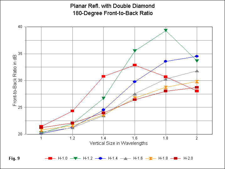
The double diamond's front-to-back behavior in Fig. 9 shows at least the horizontally smallest reflectors--if not the third also--with peak 180-degree values within the range of reflectors used in this exercise. The shape of the curves for the various horizontal dimension lines suggest that there is a "favored" width, namely, 1.2 m. However, this conclusion would required a considerable number of additional reflectors to confirm it. Peak values are not the sole interest that we might have in the graph. If we compare the curves for both the bobtail curtain and double diamond in this episode with the front-to-back curves for the other drivers covered in Part 1 and Part 2, we shall discover that the latest driver assemblies are the only ones with minimum values above 20 dB. Nevertheless, we should hold this note in abeyance until we reach the final part of this portion of the study, where we shall examine some alternative reflector wire grids.

The double diamond is no exception to the emerging rule that the 50-Ohm SWR curve is independent of the reflector size. The version shown in Fig. 10 for the maximum gain reflector would not vary in any detectable way had we used any other reflector size. The 2:1 passband extends from about 288 to 314 MHz, an 8.7% passband. Although this value is larger than most, it still is only about 1/3 the passband available to the phase-fed dual-dipole driver.

The E-plane patterns in Fig. 11 illustrate vividly a general property of planar reflectors, at least with respect to the wire-grid models that we have been using. The two patterns employ the smallest and the largest reflectors of the series. The excellent behavior of the double diamond allows us to see more clearly than with almost any other array what happens as we enlarge a reflector. The total energy in the rearward direction tends to decrease. The peak rearward lobes are down only about 20 dB with respect to the forward gain when using the smallest reflector. For the largest reflector, the peaks (noting that there are now 5 rather than 3) are down about 28 dB. In exchange--since the energy must go somewhere--the forward lobe develops a wider beamwidth as the reflector grows. The growth is modest--from 60 to 72 degrees--but is still noticeable.

The most interesting changing property of H-plane patterns requires that we use a constant vertical size with a varying horizontal dimension, as shown in Fig. 12. As we increase the horizontal dimension of the reflector, the pattern changes in the regions that are about 90 degrees off the heading for maximum gain. With a narrow reflector (H = 1.0 m), there are no 90-degree nulls, but only a tapering off of gain as we move through the region toward the rearward area. However, by the time we reach the widest reflector, the front-to-side ratio has reached a very high value, as the pattern insets clearly show.
With respect to the models used in this exercise, the double diamond driver array counts as a high-performance star within the group. It almost matches the bobtail curtain in maximum possible gain, but has none of the bobtail's pattern aberrations. At a reflector size yielding maximum gain, it exceeds most of the other drivers in front-to-back ratio. Of the higher-gain drivers, it has the widest SWR bandwidth with the exception of the phase-fed dual dipoles. Indeed, if the need is operating bandwidth, the dual-dipole driver with its 100-Ohm phase lines would be the top selection. For spot frequency use, the double rectangle, the bobtail curtain, and the double diamond might be the best choices. However, for construction simplicity, the single rectangle and the single dipole offer good performance. For H-plane beamwidth, the single dipole has a 20-30-degree advantage over the higher-gain arrays within the group. Remember that there is only a 2 dB forward gain difference between the worst and the best performers in the entire collection of planar reflector arrays.
From Tentative to Fairly Definite: Some Conclusions
At the beginning of this episode, we repeated some tentative conclusions reached on the basis of the first two parts of this study. Given our excursions through two more candidates as drivers with no significant changes of behavior trends, we may now convert those conclusions into something definite.
1. The feedpoint properties of any driver so far, once established, remain the same regardless of the reflector size. Across the span of 36 reflectors used in the exercise, the maximum change in 50-Ohm SWR was from 1.01:1 to 1.09:1, although a range of 1.01:1 to 1.04:1 is more typical.2. The ideal maximum gain height of the reflector is about 1.2 m (wavelength), regardless of the driver vertical or horizontal dimension. The dense wire-grid exercise in Part 1 of the study suggests that the actual "ideal" vertical dimension may be closer to 1.3 wavelength.
3. The ideal maximum gain reflector is one that extends horizontally beyond the driver system by about 0.5 m to 0.6 m (or wavelength).
4. The phase-fed dual-dipole driver provides the widest SWR passband of any driver assembly, and at a good gain level. However, the other driver systems all offer somewhat simpler construction and fewer field adjustment challenges.
5. The bobtail curtain and the double diamond driver systems provide the maximum gain from a planar reflector array. However, almost all of the driver systems provide gain equal to what we might derive from various long-boom 5-6 element Yagis.
6. In none of the arrays does the maximum front-to-back ratio coincide with the maximum gain in terms of reflector size. If we use a front-to-rear ratio, averaging the rearward gain across the 180 degrees of rearward directions, it appears that the larger the reflector, the lower the average rearward gain and the higher the front-to-rear ratio.
7. E-plane beamwidth is generally controllable by the selection of the horizontal reflector dimension. H-plane beamwidth, once beyond the single dipole driver, is relatively constant and lacks the secondary forward sidelobes that are typical of Yagis in the same gain category.
These conclusions appear to be reasonably reliable for planar reflectors. Of course, we have not surveyed all of the possible driver systems. For example, with more complex phasing arrangements, we might use 3, 4, or more phase-fed dipoles, along with a reflector that extends horizontally about 0.5 wavelength beyond the limits of the dipole array. Despite the incompleteness of the survey, we appear to have covered most of the array types likely to be useful to the home antenna builder.
Back to Model Reliability
In Part 1, I performed an initial test on the reliability of the models used in this survey by constructing alternative reflector wire-grid structures. A fairly standard wire grid consists of wire segments that are each 0.1 wavelength long and have a diameter that is the wire segment length divided by PI. In part 1, for a limited set of denser wire grids, I used a segment length of 0.05 wavelength, with the diameter of the wires also halved. The test showed--over the span of reflectors modeled--that the gain and front-to-back values for the new reflectors do not vary from the ones for the standard reflector up to the first decimal place in the reports. As well, resistance and reactance reports varied at most by a few hundredths of an Ohm.
Before we leave the study of planar reflectors, we might carry that investigation further to cover--at least in sample form--all of the drivers that we have examined. As well, we might--by judicious selection of a reflector size--look at not only the standard and the first increase in wire-grid density, but as well at a second density increase.
Every doubling of wire-grid density increases the number of segments in the reflector by a factor of about 3.9. I began with a reflector that is 1.4 m (wavelength) horizontally and 1.2 m (wavelength) vertically. The standard wire-grid with 0.1 wavelength segments produces a reflector with a modest 362 segments. Doubling the density by using 0.05 wavelength segments increases the number of reflector segments to 1396. The final step to a 0.025 wavelength segment requires 5480 total reflector segments. Modeling run time increases exponentially with the number of segments. Hence, I chose a single sample reflector size to use on all of the drivers. As well, a 2.0 by 2.0 wavelength reflector would have required 12,960 segments, which exceeds the limits of the NEC-4 core (unless one uses GX or symmetry techniques). Fig. 13 shows a comparison of a sample wire-grid and its double-density counterpart to illustrate the rate of segment growth.

In spite of the limitations of the test, the results are worth scanning in tabular form. Each driver apears in the order presented, with data for the sample reflector using the 3 degrees of density.
Single Dipole
Density             Free-Space     Front-to-Back     E-BW       H-BW       Impedance        50-Ohm
Level               Gain dBi       Ratio dB          degrees    degrees    R+/-jX Ohms      SWR
X1                  9.27           19.19             54         82         49.29 - j1.18    1.03
X2                  9.25           19.28             54         82         49.28 - j1.33    1.03
X4                  9.24           19.25             54         82         49.36 - j1.34    1.03
Max. Difference     0.03            0.09             --         --          0.08    0.16    ---
Phase-Fed Dual Dipoles
Density             Free-Space     Front-to-Back     E-BW       H-BW       Impedance        100-Ohm
Level               Gain dBi       Ratio dB          degrees    degrees    R+/-jX Ohms      SWR
X1                  10.82          19.03             56         54         97.91 - j2.29    1.01
X2                  10.77          19.18             58         54         97.96 - j2.32    1.01
X4                  10.75          19.22             58         54         98.05 - j2.39    1.01
Max. Difference      0.07           0.19              2         --          0.14    0.10    ---
Single Rectangle
Density             Free-Space     Front-to-Back     E-BW       H-BW       Impedance        50-Ohm
Level               Gain dBi       Ratio dB          degrees    degrees    R+/-jX Ohms      SWR
X1                  10.37          19.43             56         63         49.76 - j0.39    1.01
X2                  10.34          19.59             56         63         49.79 - j0.32    1.01
X4                  10.32          19.60             58         63         49.87 - j0.31    1.01
Max. Difference      0.05           0.17              2         --          0.11    0.08    ---
Double Rectangle
Density             Free-Space     Front-to-Back     E-BW       H-BW       Impedance        50-Ohm
Level               Gain dBi       Ratio dB          degrees    degrees    R+/-jX Ohms      SWR
X1                  10.86          19.48             58         54         49.59 - j0.30    1.01
X2                  10.82          19.69             60         54         49.62 - j0.33    1.01
X4                  10.80          19.75             60         54         49.69 - j0.36    1.01
Max. Difference      0.06           0.27              2         --          0.10    0.06    ---
Bobtail Curtain
Density             Free-Space     Front-to-Back     E-BW       H-BW       Impedance        50-Ohm
Level               Gain dBi       Ratio dB          degrees    degrees    R+/-jX Ohms      SWR
X1                  11.20          22.83             57         48         49.70 + j3.41    1.07
X2                  11.16          23.25             57         48         49.68 + j3.31    1.07
X4                  11.14          23.40             57         48         49.74 + j3.27    1.07
Max. Difference      0.06           0.57             --         --          0.06    0.14    ---
Double Diamond
Density             Free-Space     Front-to-Back     E-BW       H-BW       Impedance        50-Ohm
Level               Gain dBi       Ratio dB          degrees    degrees    R+/-jX Ohms      SWR
X1                  11.10          21.24             56         52         49.63 - j0.61    1.01
X2                  11.06          21.50             56         52         49.61 - j0.72    1.02
X4                  11.04          21.54             56         52         49.71 - j0.74    1.02
Max. Difference      0.06           0.30             --         --          0.10    0.13    0.01
Besides giving us a comparison among reflector wire-grid densities as one (but not the only) test of model reliability, the table provides a snapshot of some of the differences among the arrays in terms of typical beamwidths, gain levels, and front-to-back values. It is clear, for example, that the single dipole provides the greatest H-plane beamwidth, while the bobtail curtain provides the narrowest. The E-plane beamwidth varies with reflector size, but does not vary significantly among the types of drivers. Although only one of the drivers shows its maximum possible gain with the reflector size used in the test, the gain levels accurately show what each driver can achieve in relative terms.
The internal differences for each driver are minuscule as a function of the density of the wire-grid used in the modeled reflector. Only the bobtail curtain shows a noticeable range of front-to-back ratios, and that result stems from the pattern tilt. In practical terms, the re-modeling of the reflector tends to validate the values yielded by the standard (X1) grid, and certainly the trends hold good whatever the numbers in the final decimal places of the modeling reports. How close the values are to each other shows up clearly in Fig. 14, which overlays the E-plane and H-plane patterns for the single rectangle driver. Beneath the red line is a blue-line pattern having the identical shape throughout for both orientations.

Remember that this test only shows that the results of using the standard wire-grid with 0.1 wavelength segments are valid witin the context of what NEC-4 can calculate as the performance of the arrays. The average gain test values (all above 0.99, where 1.00 is perfect) provide additional evidence of model adequacy. However, the tests do not provide an external confirmation of the models by comparison with carefully constructed and measured lab or range antennas. That added confirmation lies beyond the scope of this study, but would be a necessary step, should one wish to develop operational planar reflector arrays.
Nevertheless, the models used in this study can provide guidance to anyone wishing to build a one-of-kind planar reflector array for some specific use. It is likely that, at UHF especially, the lumps and bumps called construction variables will occasion more field adjustment than any lack within the models.
Updated 04-01-2005. © L. B. Cebik, W4RNL. This item originally appeared in antenneX March, 2005. Data may be used for personal purposes, but may not be reproduced for publication in print or any other medium without permission of the author.