 Some Notes on Modeling Hybrid Transmission Line Stubs
There are many uses for hybrid transmission line stubs, but they tend to fall into two categories. First, the use of a hybrid stub allows the designer to place the terminating end of the stub at a desired distance from the circuit or antenna end of the line. Second, the hybrid stub allows the user to modify the stub reactance with fixed reactances so as to achieve a wide range of desired values of either inductive or capacitive reactance.

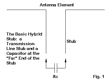
The general treatment of the hybrid stub underlying Fig. 2 is as an open stub with a capacitive reactance across the far terminals. This reactance is viewed as equivalent to a parallel capacitor placed across the antenna (or circuit) terminals of the stub. Unfortunately, this treatment appears to misconstrue the hybrid stub.

Fig. 3 shows a more useful interpretation of the hybrid stub. The capacitive reactance across the terminating end of the stub is in series with the reactance of a shorted stub. Although the insertion of a capacitor creates an open DC circuit, the RF path remains complete. Hence, the net reactance of the hybrid stub is simply the sum of the stub reactance and the capacitive reactance.
If the (shorted) stub is less than 1/4 wavelength long, then its reactance is inductive. Between 1/4 and 1/2 wavelength, the stub is capacitively reactive, returning to an inductive reactance for length between 1/2 and 3/4 wavelength.
The fixed reactance at the far end of the stub can be, in principle, either inductive or capacitive. Inductive reactances are rarely used, since the Q of inductors tends to be low enough to introduce unwanted losses in the hybrid stub. The higher Q of capacitors tends to offer much lower loss and greater ease of varying the net reactance of the hybrid stub. (Remember that the stub itself is not without some loss.)
The hybrid stub, according to this construal, is always shorted, with a series reactance at the far terminals. Perhaps a test NEC-4 model can both test and illustrate the hybrid stub principle.

Fig. 4 shows the general layout of the hybrid stub. At a frequency of 3.6 MHz, a wavelength is about 273.2' long. The recommended minimum segment length is about 0.001 wavelength, calling for a separation of the transmission line wires of minimally 0.273'. For the tests, I used a spacing of 0.33' or 3.96". To ensure that I introduced no inaccuracies be virtue of having adjacent segments of significantly different lengths, I used 3 segments per foot for both the transmission lines wires and the antenna element wires. The result was a series of Yagi test models having between 800 and 850 total segments.
One caution is useful at this point. Because the transmission line wires have equal and opposite currents, their net radiation is virtually nil. Under these conditions, a poor model of a transmission line stub will not show itself in the average gain test (AGT). Poor to precise models all showed an AGT of 1.0 on NEC-4, indicating that the value is almost solely a product of the wire antenna elements themselves. Remember that the AGT is a necessary and not a sufficient condition of model adequacy. Therefore, I can only recommend that the test cases used here not be replicated in software having an insufficient total segment count.
The reason for using AWG #14 wire for both the element and the transmission line is to ensure that NEC yields accurate results. NEC has a known potential error weakness wherever there are angular junctions of wires with different diameters.
We can calculate with very good precision the characteristic impedance (Zo) of the #14 wires spaced 3.96" apart.

The most accurate equation (1) for the calculation defines S as the center-to-center spacing of the round conductors and d as the conductor diameter, assuming conductors of the same diameter. Although we may invoke this equation for any parallel transmission line, it is only necessary where wires are very closely spaced. Most often--for more widely spaced wires, we use a more familiar equation (2) to calculate the Zo of the line:

There are many operating aids to perform the calculation for us, and the Zo of the stub line used in these exercises is about 577.6 Ohms.
From the Zo, along with the line velocity factor (VF)--which is 1.0 in this case--we can calculate both open and closed (shorted) stub lengths to arrive at any desired reactance. As well, we can calculate the required stub length for a desired reactance. However, the calculations will require that we register the line length in electrical degrees.

Equation (3) is handy for determining the electrical length in degrees from the line length in either meters or feet. To go the other way, we use equation (4):

where K is 1.20 for lengths in meters and 0.366 for lengths in feet,
Once we can work with electrical lengths in degrees, we can handle the correlation of stub length and reactance. For a closed or shorted stub, we use the equations in (5):

where Xc is the reactance of the closed or shorted stub. Note that the equation applies to any line length, as the tangent of the ratio will change signs as we pass the 90-degree point. However, when calculating lengths, we shall have to adjust the lengths by adding 180 degrees when the length values are negative.
Likewise, we can move from line length to reactance and back again by using the equations in (6):

where Xo is the reactance of the open stub. Again, we shall have to add 180 degrees to line lengths when the results are negative.
There are two phenomena not accounted for in the calculation of the lines by means of the classical equations. First, the calculations do not account for the small line losses that result from the less-than-perfect conductivity of copper wire. These losses are quite small, but will show themselves as slight modifications of the feedpoint impedance, whether the stub attaches to the driven element or to a parasitic element. Second, the equations do not account for stub-end phenomena, such as the characteristics of the wire that shorts a closed stub. These effects are small and show themselves most vividly when the stub is very short. In such cases, the shorting wire becomes a more significant percentage of the total length of wire in the stub.

I first modeled the antenna to a set of free-space operating characteristics at 3.6 MHz. The driver used 393 segments and reflector used 411. The NEC-4 results are as follows.
Gain (dBi)            Front-to-Back         Feedpoint Impedance
                      Ratio (dB)            (R +/- jX Ohms)
5.94                  10.55                 37.18 - j 1.709
Because this is an exercise involving numerical progressions rather than an operating design, reported values use the full set of decimal places.
I then added to the reflector a shorted stub as described earlier. I calculated the stub in increments of 10 Ohms inductive reactance. On the shorting wire, I introduced a capacitive reactance of the same absolute value as that calculated for the stub. (The reactance can be replaced by its corresponding capacitance with no change of results for this single-frequency test.) The following table provides the results.
Stub Xl    Stub L     Gain       F-B Ratio        Feedpoint Impedance
(Ohms)     (feet)     (dBi)      (db)             (R +/- jX Ohms)
 10        0.753      5.98       10.48            36.45 - j 1.988
 20        1.505      5.98       10.47            36.47 - j 2.001
 30        2.257      5.97       10.47            36.57 - j 1.980
 40        3.007      5.96       10.47            36.71 - j 1.947
 50        3.755      5.95       10.48            36.88 - j 1.901
 60        4.501      5.93       10.49            37.17 - j 1.817
 70        5.244      5.92       10.49            37.28 - j 1.797
 80        5.985      5.90       10.49            37.53 - j 1.729
 90        6.722      5.89       10.49            37.70 - j 1.691
100        7.455      5.88       10.49            37.88 - j 1.650
Overall, the introduction of a capacitive reactance at the far-end terminals of the shorted stub results in a confirmation of the construal of the hybrid stub, since the antenna returns in each case to its original operating characteristics when the introduced capacitive reactance compensates for the calculated value of the inductive reactance of the stub. Fig. 6 overlays the free-space E-plane patterns of the original array and of the version using a 100-Ohm stub and a corresponding capacitive reactance in the shorting wire.

The progression of feedpoint impedance values shows in part the effect of the increasing (although operationally insignificant) losses as the stub wires grow longer. However, there is an ambiguity in the results if we read them from the gain and front-to-back columns. The gain of the version with the shortest stub is actually higher than that of the original beam without any reflector stubbing. However, if I add a reflector load to the original beam consisting of -1.5 Ohms (capacitive reactance), then the gain becomes 5.98 dBi with a front-to-back ratio of 10.49 dB and a feedpoint impedance of 36.48 - j 1.961 Ohms.
The source of the slight offset might arise from several sources. 1. The characteristic impedance calculation might be slightly off relative to NEC-4's calculation of the effects of paralleling the wires. 2. The shorting wire may contribute to the offset in part or in whole. 3. The length calculations may not correspond with absolute precision between the calculations and the NEC-4 calculations.
The practical output from the existence of the offset is simple: always use a variable capacitor when initially setting a system following these general parameters. This practice can also compensate for minor differences between the actual line velocity factor and the value assumed for calculations.
However, in principle, the system used to construct a model of the hybrid transmission line stub shows excellent results both as a confirmation of the operation of the stub and as an illustration of what is possible.

As a test case, let's consider the driver-reflector Yagi shown in Fig. 7. The basic Yagi consists of a driver and a parasitic reflector that is the same length as the driver. The basic configuration requires a reflector load of 65 Ohms for the array to yield the following free-space operating properties.
Gain (dBi)            Front-to-Back         Feedpoint Impedance
                      Ratio (dB)            (R +/- jX Ohms)
6.09                  10.30                 34.75 - j 0.603
The load for this Yagi consists of a shorted stub having the same characteristics as the one used in the preceding example. Everything is AWG #14 wire, with the stub using a spacing of 0.33' (3.96").
Now let's lengthen the stub to a calculated length for a 100-Ohm inductive reactance. The theoretically required capacitive reactance for returning the stub to a net of 65 Ohms inductive reactance is -35 Ohms. The following table shows the reported operating properties with a small range of capacitive reactance values.
Cap. Xc          Gain       F-B Ratio       Feedpoint Impedance
(Ohms)           (dBi)      (db)            (R +/- jX Ohms)
-35              6.07       10.04           34.32 - j 1.090
-34              6.05       10.15           34.81 - j 0.849
-33              6.03       10.25           35.31 - j 0.614
Although the differences are well below the level of practical concern, they are interesting. The simply calculated value of inductive reactance restores the array gain, but shows a lower front-to-back ratio and lower resistive component to the impedance. Subtracting 1 Ohm of capacitive reactance restores the feedpoint impedance, but lowers gain and does not bring the front-to-back ratio back near its original value. Subtracting a second Ohm of capacitive reactance restores most of the front-to-back ratio and sets the feedpoint reactance very close to its original value, but at a cost of slightly lower gain and a slightly high feedpoint resistance. The question (of academic interest, mostly) is which of the 3 options best reflects array performance.
Essentially, the last option of using -33 Ohms of capacitive reactance seems most accurate to reality. Lengthening the stub slightly increases wire losses in the array. These losses will slightly reduce gain and--even though the loss is in the reflector--slightly elevate the feedpoint resistance. However, the front-to-back ratio will be sustained. Hence, moving toward an equality of feedpoint reactances appears to best equate the altered array with the original.
As we noted in the first test, there is a slight offset between the calculated value of capacitive reactance and the value required for the best level of equality, even with an appreciable stub length. The 2 Ohm differential is well within the range of practicality, but once more suggests that when implementing any hybrid stub, a variable capacitor best serves the needs of initial testing.

Despite the use of a hybrid stub, the resulting pattern shows no aberrations. Fig. 8 overlays the free-space E-plane patterns for the original and the modified arrays using the -35 Ohm option.

Let's turn the tables and create a driver-director Yagi using a near-resonant driver and a director of the same length, as shown in Fig. 9. To function as an effective director, we shall have to add capacitive reactance as a director load. For the free-space operating values in the following table, I added a load of -60 Ohms to the director.
Gain (dBi)            Front-to-Back         Feedpoint Impedance
                      Ratio (dB)            (R +/- jX Ohms)
5.85                  22.28                 22.16 + j 1.188
Now let's add to the director a shorted stub with an inductive reactance of 60 Ohms. Using our #14 wire and 3.96" spacing, our line has a Zo of 577.6 Ohms, calling for a stub length of 4.50'. Theoretically, we must now increase the loading capacitor (at the stub short) to -120 Ohm capacitive reactance. The following values emerged from the exercise.
Cap. Xc          Gain       F-B Ratio       Feedpoint Impedance
(Ohms)           (dBi)      (db)            (R +/- jX Ohms)
-120             5.87       18.58           20.12 + j 3.626
-124             5.80       21.85           22.37 + j 1.392
Although the use of the theoretically correct value best preserves array gain, it results in off-target values for the front-to-back ratio and the feedpoint impedance. One of the benefits of using a driver-director array as a test vehicle is that the closely spaced elements exhibit a narrower passband than a driver-reflector array. Hence, smaller changes in component values yield larger changes in performance.
Increasing the capacitive reactance by 3% restores virtually all of the array performance except for that small amount lost in the resistivity of the stub wire. Once more, the implementation of a hybrid stub would require a variable capacitor for initial testing before replacing the unit with a fixed value. (Of course, one might retain the variable capacitor and remotely tune it to maximize array performance over a wider frequency range than would be possible with a fixed capacitor.)
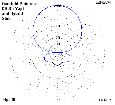
The version of the array using the stub and -124 Ohms of capacitive reactance performs in practical terms as well as the original array. Fig. 10 overlays the free-space E-plane patterns for this version and the original array as a demonstration of the operational equivalence of the two designs.
However, using wire stubs is necessary. The NEC TL facility for creating non-radiating transmission lines cannot be directly employed for the exercise. Ideally, the TL facility would permit the use of any diameter element and would remove the wire losses of the stub from consideration when evaluating the results. (However, those losses are real and a designer must account for them when constructing an actual array using stubs.)

Fig. 11 shows why the TL facility is not apt to the present task. The models require that we place a load on the stub terminating wire. With wire stubs, the load is centered within the wire space with the parallel lines terminated at the wire ends. However, loads are always in series with transmission lines created by the TL facility of NEC. As a result, a load added to the wire used to terminate a stub would actually fall outside the lines making up the stub itself.
There are means of placing a load on the terminating wire in series with the terminals. However, not all implementations of NEC permit its use. We may specify admittance values (called real and imaginary for the more common terms of conductivity and susceptance) at the TL termination. Susceptance is simply the inverse of reactance. Hence, it is possible to load a transmission line in some implementations of NEC.
The use of such terminating loads is always in terms of admittance and never in terms of capacitance or inductance. Consequently, the values are applicable to one select frequency and do not vary with changes in frequency, as do LD-type loads specified in terms of capacitance and reactance. Since admittance loads at the terminations of TL transmission lines are not commonly used by beginning modelers, I have not used them in this exercise, but have let the ambiguities stand.
1. Reversible wire arrays: Consider a 3-element parasitic array with identical lengths for the elements. In most cases, the reflector will require a shorted stub to optimize its electrical length. The director will require an open stub to optimize its length. Assuming, of course, that we choose to use stubs for this work.
However, we have an alternative. Let's use hybrid stub systems throughout. We may lengthen the reflector stub by an amount od reactance equal to the minimum reactance available from a capacitor (or system of paralleled capacitors), plus a bit more. Then we may use the capacitor to reduce the net inductive reactance and possible to tune the reflector.
We may also treat the director similarly, by using a shorted stub equal to the capacitors minimum reactance and then adding capacitive reactance in the amount necessary to tune the director for optimal array performance.
If we choose to do so, we may lengthen each stub by 1/2 wavelength with no change in the tuning range of each variable, thus placing the variable components near to ground level for easier weather protection. However, we must take into account the added losses of the longer stub lines when evaluating the aptness of these design moves. Line losses from the system may be acceptable at 160 or 80 meters, but they may become excessive in the upper HF range.
Reversing the array is a simple matter if the lines extend to a central location. We may simply switch the director and reflector capacitors, including in the reflector side that added line length for that operation. At 160 meters, such a tunable/switchable system may permit a doubling of the normal operating passband with wire beams--and permit the user to achieve a higher front-to-back ratio away from the initial design frequency.
2. Positioning a loading component: A length of shorted transmission line stub in conjunction with a capacitive loading element can be used to electrically lengthen an antenna element. As well, proper selection of the line length and the capacitor reactance hold two advantages. For a fixed capacitor termination, we may change the electrical length of the element simply by changing the capacitor. As well, we may run both the capacitor and stub within the physical element, thus using the ready weather protection offered by the element. My old GAP VI appears to use just this sort of system to achieve a narrow-band 80- or 75-meter resonance.
3. Tuning a short monopole: Most vertical monopoles for 80 and especially 160 meters are shorter than 1/4 wavelength. Hence, tuning them for optimal operation involves one or more of a number of techniques to overcome the low feedpoint resistance and rapidly changing feedpoint reactance. The complexity of some tuning systems is a wonder to behold.

Fig. 12 shows an alternative system that applies to monopoles longer than 1/8 wavelength and shorter than 1/4 wavelength. We shall explore that restriction in a moment. Let us use a system by which we can establish resonance across one of the lower ham bands.
Over the range of 160 meters, a 1/8 wavelength monopole changes its resistance by only abut 2 Ohms or so. Hence, if we could control the reactance, we might use a fixed network to match the low feedpoint impedance to a standard 50-Ohm coaxial cable. Such fixed networks are normally more weather durable than networks requiring the remote tuning of variable components--assuming that both are assembled within equally weather-resistant packages.
Instead of using a loading coil or other means of electrically lengthening the radiator, let's use a hybrid stub system. With the correct combination of line length and capacitors, we can alter the inductive reactance at the monopole by wide amounts--and take into account the potential shifts in frequency. The line length--alone or plus multiples of 1/2 wavelength--might even permit the capacitor system to be indoors with the operator.
There are some restrictions in the use of this type of system. For shorter monopoles, we require stub lengths providing higher values of inductive reactance. Stub lengths close to 1/4 wavelength show rapid changes of reactance with small changes of length. (Remember that stub length is a tan function, which goes to an indefinitely high value at exactly 1/4 wavelength.) Indeed, working with lengths close to 1/4 wavelength at the lowest frequency of use may result in a line already longer than 1/4 wavelength at the highest used frequency. Hence, keeping the required inductive reactance as low as may be practically possible gives the system more flexibility. One way to do this is to increase the monopole height well above the 1/8 wavelength point.
As well, the capacitor tuning system requires calculation of its reactance span for both the lowest and highest frequencies of use, and these values must be correlated with the basic stub length to ensure that the capacitors will have sufficient range to tune the antenna across the entire span of frequencies to be used.
If one can live within these restrictions, then there is an added advantage to the system. Tuning need only locate the lowest SWR point, given the fixed network at the antenna base. The fixed network may use the lowest working Q obtainable for maximum efficiency. Despite the losses in the stub line, the hybrid system is likely to have lower losses than most (but certainly not all) other means of electrically lengthening the antenna.
These sample applications only scratch the surface of the potential for hybrid transmission line stub systems. You may already know of others.
At root, however, this exercise has aimed at better understanding and properly modeling the hybrid transmission line stub system.
Updated 05-01-2002. © L. B. Cebik, W4RNL. Data may be used for personal purposes, but may not be reproduced for publication in print or any other medium without permission of the author.