One of the most difficult tasks in designing a multi-band 2-element quad beam is obtaining full band coverage. This problem has two dimensions. One dimension involves obtaining at the antenna an SWR that is less than 2:1 relative to the impedance of the main feedline all across each of the bands covered by the beam. The second dimension covers other important operating parameters, such as adequate gain and front-to-back ratio across each band.
The design that we shall show covers only the widest amateur upper-HF bands: 20, 15, and 10 meters. For the narrower bands, 17 and 12 meters, one may use a dual-band quad with a common feedpoint, as shown in Part 3 of the recent series of articles analyzing the element interactions and the use of a common feedpoint. The present beam uses separate feedpoints and restricts coverage to only 3 bands in order to obtain between adjacent bands the largest feasible frequency ratios. The result is relevantly similar band-to-band performance and a set of manageable feedpoint resistance and reactance values. By judicious use of a 75-Ohm matching line on each band, the 50-Ohm SWR values will be under 2:1 across all passbands.
The design specifically excludes the narrow bands, even though we might have thrown in loops for them. In the latter portion of our discussion, we shall examine a pair of 5-band designs previously analyzed in Volume 1 of Cubical Quad Notes. The exercise will clearly indicate why a 3-band limit within the upper HF range is desirable for a 2-element quad.
The Physical Design
The tri-band quad sketched in Fig. 1 derives from the same set of monoband 2-element quads that we have used as the basis for dual-band quad behavior. In fact, it is simply a refined version of the sample tri-band, 2-element quad shown in Part 2 of "Sneaking Up on 2-Element Common-Feed Quads." The design frequencies for the 3 bands are 14.14, 21.19, and 28.4 MHz. At these frequencies, the monoband quads are set for resonance (within +/-j 1 Ohm) and for peak 180-degree front-to-back ratio. At the design frequency, the free-space forward gain is 7.04 dBi on all frequencies. The designs derive from calculations based on a large collection of models and regression analysis. The programs appear in Volume 2 of Cubical Quad Notes and require the designer only to input the element diameter and the design frequency. The model outline sketch on the left shows the positions of the 3 separated feedpoints, but not the match-line needed to feed the array with a 50-Ohm main cable. Of course, only one feedpoint would be active at any one time, so the array requires a remote switch on the mast or 3 separate feedlines to the shack.

In adapting these monoband designs for a tri-band quad, I am using spider construction. It requires non-conductive support arms that "lean" forward and backward about 31 degrees relative to a vertical line created by the mast is it reaches the hub (and virtually passes through to continue that line). This angle is the average of the angles for each of the 3 bands. Since AWG #14 copper wire has a different diameter on each band if we measure it in wavelengths, the angle varies slightly from band to band. However, the small discrepancy in driver-to-reflector spacing will make no practical difference in the performance. The loop lengths are much more sensitive to changes. If a builder wishes to use the specified spacing between elements, he or she may attach a fiberglass or similar rod between the forward and rearward support arms near to the elements for each band.
Table 1 provides the required dimensions for the tri-band 2-element quad. All dimensions are in inches. The side lengths are for full sides. Modelers may need to divide those numbers by 2 in order to center a NEC or MININEC model at the center of the coordinate system. Later, all performance numbers will use free-space values. The gain of the array over ground will increase by about 5 or more dB (depending upon the actual height), but the front-to-back ratio will remain unchanged. If the array is at least 1 wavelength above ground, the impedance will be virtually unchanged from the free-space value. Even at lower heights, the quad is less prone to ground-induced impedance changes than a beam using linear elements. The quad loop is actually two dipoles spaced about 1/4 wavelength vertically, with the ends brought together at the zero-current points. When measured as a function of the elevation angle of the main lobe and the same angle for a dipole or 2-element Yagi, the working height of a quad is about 2/3 of the distance from the bottom to the top horizontal wires. For non-critical purposes, the centerline or the hub height will do as the conventional marker of antenna height.

The dimensional table lists the sizes of the foundational monoband quads as well as the dimensions used in the tri-band version. For each band, the driver-to-reflector spacing remains unchanged. On 20 meters, the tri-band driver is longer than the monoband driver, but the tri-band reflector is shorter. On 10 meters--the innermost set of loops--the tri-band driver is shorter than the monoband driver, but the tri-band reflector is longer. In the recent study of dual-band interactions ("Adjacent-Band Quad Behavior"), I noted that when an element set undergoes interactions with both an inner and an outer set of elements, the middle set is not influenced equally. Hence, the effects on both the middle driver and reflector are not simply canceled out. In the case of the present tri-band design, the 15-meter driver and reflector are both shorter than in the monoband design on which they rest.
Each driver requires a match-line consisting of a length of 75-Ohm cable. The 20-meter quad uses a relatively precise 1/4 wavelength. On 15 meters, 1/4 wavelength is about 139", while on 10 meters, 1/4 wavelength or close to 104". The prescribed lengths for 15 and 20 are both shorter. When we examine the modeled performance data for the quad, we shall better understand why the lines use less than a full quarter wavelength of impedance transformation. Since the quad uses square rather than diamond construction, the match-lines (or even directly connected main feed lines) require support. I recommend the use of a UV-protected rope running from the hub through each feedpoint. You may then tape or otherwise clamp the match-lines to the rope, since coaxial cable is not designed to support loads--not even its own weight for very far. Of course, there is no rule that requires a coaxial match-line. Parallel 75-Ohm transmission line--if available or if you can fabricate it--will work as well. However, at the remote switch or the transition to a 50-Ohm coaxial feed line, you will need a 1:1 balun or ferrite-bead choke to suppress (or, more correctly, attenuate) common-mode currents. Such a device is good practice at the remote switch even if you use coaxial cables for the match-lines.
The dimensions for the tri-band quad are more finicky than those for a monoband quad (but less finicky than the dimensions for a 5-band quad). Therefore, you will wish to use careful construction methods to avoid the need for nearly endless field adjustments. The support arms should be non-conductive. As well, the method for attaching the elements to the arms at the element corners should make use of non-conductive materials or hardware. Metal clamps or loops can create 1-turn inductors at the element corners. The 4 required for each element may be enough to significantly detune the element. There are methods of compensating for such methods of fastening, but they tend to be long and tedious. If you are constructing quads commercially, going through the compensation process once for each new design may well be worth the effort to obtain a desired set of corner fixtures. However, for a one-of-a-kind antenna that grows out of one's workshop, giving some extensive forethought to designing an effective means of arm-to-element attachment that involves only non-conductive materials may actually shorten the construction time considerably.
TriBand Performance
The goal of the design was to obtain--to the degree possible--all of the performance potential offered by the monoband quads that form the basis for each element set. Studies in element interaction suggest that we may not be able to succeed completely. However, we may be able to develop a very good tri-band quad. As a yardstick, a short-boom Yagi will show about 7+ dBi free-space gain. Here, a short boom is about 8' on 10 meters and 16' on 20 meters. (A long-boom 3-element Yagi might develop just over 8-dBi free-space gain, where a long-boom on 20 is about 24' and on 10 is about 12'.) A 2-element driver-reflector Yagi may be able to manage about 6 dBi free-space gain. The 2-element Yagi front-to-back ratio will run between 10 and 12 dB across any of the wider amateur upper HF bands. However, a well-designed short-boom 3-element Yagi may achieve 20 dB across 20 and 15 meters and at least 17-18 dB across 10 meters. Although it is possible to design a 2-element driver-reflector Yagi for direct connection with a 50-Ohm cable, most higher-performance Yagis below 6 elements require a matching network to raise a lower feedpoint impedance to the usual 50-Ohm cable impedance. In general, a 2-element quad can match the gain of a short-boom (but not a long-boom) 3-element Yagi, but the quad suffers fairly narrow bandwidth for its front-to-back performance. Under the best conditions, a monoband quad will show band-edge front-to-back ratio values somewhere between 12 and 18 dB, depending on the passband width. For this reason, I have used an initial monoband quad design with the broadest possible bandwidth for both the front-to-back and impedance performance.
Element interactions in a multi-band beam will limit our ability to achieve full monoband performance. However, Gain is not one of those limitations. As shown by the graph in Fig. 2, the gain curves are normal or above normal for 2-element monoband quads. The design frequency is at the 40% marker on the steps up each of the bands. At that point, the monoband gain is about 7.04 dBi, and even the 20 meters elements achieve this level. The more inward loop sets manage slightly higher gain levels. However, the difference in not sufficient to be operationally noticeable. We may note in passing that the closer a set of elements is to the outer position, the steeper is the slope of gain decrease with rising frequency.

Like all 2-element driver-reflector parasitic structures, the gain decreases as the frequency increases. The rate of descent of even the steepest curve is not far from the monoband curve. (Any parasitic array with at least one well-designed director will show a reverse curve, that is, one that increases in gain with rising frequency. For example a typical short-boom Yagi would show a curve that is virtually the reverse of the quad gain curves, but with very similar band-edge gain values.)
One reason for tweaking the dimensions of the tri-band beam elements was to place the front-to-back peak as close as feasible to the design frequency on each band. The curves in Fig. 3 measure the success of that move. I wanted to find out if centering the front-to-back peak at the design frequency would yield relatively equal band-edge values, as the process did for the monoband quads. The band-edge front-to-back values are only slightly less equal than for the monoband beams on which this design rests.

For comparative purposes, the monoband 20 meter quad achieves about 16-dB front-to-back values at the band edges. The tri-band 20 meter elements fall from 1 to 2 dB below that value. The 15-meter monoband quad shows about 18-dB at the band limits. The 15-meter elements of the tri-bander are again about 1-2 dB lower. On 10 meters, the monoband quad reached a very high peak level, with about a 14-dB front-to-back ratio at 28 and 29 MHz. The inward position of the 10-meter elements in the triband quad prevents us from achieving the very high peak front-to-back value, but the band-edge values are 2 to 3 dB higher than for the monoband model.
We must add two notes to these reports of modeled performance. First, the actual peak front-to-back ratio--as a 180-degree value--will not be as operationally significant as it is dramatic in the graphs. Not only is the peak a narrow-bandwidth phenomenon, it is also a dimple in the overall rearward gain levels of the array. Second, the values appear in the graphs due to simple changes in the modeled array geometry. It is also unlikely that one will be able to precisely place the peak value with respect to frequency. (The best way to tell is to perform tests with a nearby patient friend, with the quad pointed directly away from that station.) The final construction-ending test is the adequacy of the front-to-rear overall performance, especially at the band edges.
The band-edge patterns are quite unlike those at the design frequency or at the nearby band center. To show the range of likely patterns, Fig. 4 presents a gallery of free-space E-plane (azimuth) patterns for each of the bands, using the band limits and the band center as snapshot frequencies.

The patterns show both good and not quite so good things about 2-element quad performance in a tri-band array. The very good aspect of the gallery views is the fact that the patterns for each band are very similar for corresponding positions in each band. The design constraints brought to the project have resulted in a quad that performs in a very similar manner on each of the included bands. Less than very good is a fundamental limitation in the rearward lobes of a quad when used on a wider amateur band. Note that the lines that indicate the strongest rearward gain have similar values at the lower band edge and at mid-band: very roughly 15 dB below the main forward lobe. However, at the upper band edge, the worst-case front-to-back ratio is down to about 12 dB or so, even though the 180-degree value is somewhat higher. We would find the same pattern of rearward lobes, even using monoband quads.
The next step in our review of tri-band quad performance takes us into the region of the feedpoint impedance. The monoband quads showed design-frequency resonant impedance values between 130 Ohms at 20 meters to 136 Ohms at 10 meters. Those values allow us to use a standard 1/4 wavelength 75-Ohm match-line on any of the monoband quads to obtain a good match to a 50-Ohm main feed cable and still have an acceptable SWR across each of the bands.

Fig. 5 shows what happens to the feedpoint impedances in terms of resistance and reactance before we add any matching devices or networks. Again, the 40% marker represents the approximate design frequency for each band. At this point, we can see the crossing reactance lines at about j0 Ohms. As we learned in the study of adjacent-band quad behavior, it does not matter whether a multi-band loop set occupies an outer or an inner position. The feedpoint resistance will decrease. The 20-meter value is about 123 Ohms. Perhaps the new information offered by the tri-band quad is that as we add set of loops, the resistance decreases further as we move toward the innermost set. On 15 meters, the resonant impedance is only about 106 Ohms, and on 10 meters, it has decreased to 94 Ohms. We shall look at these values once more in the last part of these notes when we compare tri-band performance to 5-band performance.
The reactance curves are rather modest for 20 and 15 meters, partly as a function of having other element sets inward from them and partly because the bands are between 2.1% and 2.5% wide. In contrast, the 10-meter reactance curve undergoes the greatest excursion and virtually in a linear progression. The size of the excursion of reactance is a joint function of the added bandwidth (3.5% wide) and the fact that the 10-meter elements are the most inward of the bands included in this array.
Fig. 6 shows the resistance and reactance at the shack-end of the match-line prescribed for each band. On 20-meters, we can employ a 1/4 wavelength 75-Ohm line, which is about 209" at the design frequency. A corresponding 15-meter line would be about 139" long. However, a transmission line effects an impedance transformation at any length. By judicious line length selection, we can often achieve a more desirable set of resistance and reactance values across a given band. Note that the use of a 130" line on 15 yields band-edge resistance values that are very similar to those we obtain on 20 meters with the full 1/4 wavelength line. At the same time, the reactance curve for 15 meters is actually flatter than the one for 20 meters.

Important Note: The line lengths noted here are electrical lengths translated into inches. Multiply the listed electrical length by the velocity factor of the line actually used to arrive at the necessary physical line length. For most purposes, you may use 0.66 as the velocity factor for 75-Ohm lines with a solid dielectric and 0.8 for lines with a foam dielectric. However, for best precision, it may be useful to measure the velocity factor of the line used.
On 10 meters, we have less than an ideal situation. A quarter wavelength line does not yield an acceptable range of impedances, largely due to the wider range of reactance values that we encounter on this band. However, an electrical length of 95" will yield acceptable SWR values. As shown in Fig. 6, the resistance range is very similar to the range resulting from the 20- and 15-meter match-lines. However, the reactance curve is considerably wider than those for 15 and 20.
For most operators, the final measurement is simply the 50-Ohm SWR at the junction of the matchline and the main feed cable. (I am avoiding all temptation to show values that might result from taking measurements 50, 75, 100 or more feet down an actual cable with its loss factors included. These shack-end SWR values will always be lower than the values at the point where the 50-Ohm cable is closest to the antenna.) Fig. 7 shows the modeled SWR curves. The match-lines use the NEC-provided lossless cable for the match-line. However, since each match-line is 1/4 wavelength or less, the lossless values are a very good approximation of reality.

The 50-Ohm SWR curves 20 and 15 meters are very satisfactory, with the peak value just over 1.4:1. The 15-meter curve shows a lowest value that is higher than the lowest 20-meter value because the 15-meter match-line is a bit shorter than 1/4 wavelength. Had we used a perfect 1/4 wavelength line, the curve would have still been acceptable, but one end of the band would have shown a much higher value than the other.
On 10 meters, we departed the farthest from 1/4 wavelength, and the resulting SWR curve has a low value of about 1.2:1, At the band edges, the SWR is 1.8:1 or slightly higher. The result is an acceptable, but certainly not an outstanding 50-Ohm SWR curve. However, in the world of multi-band 2-element quads, covering the entire first MHz of 10 meters with under 2:1 50-Ohm SWR is itself a bit rare, especially if we wish to achieve any performance across this wide band.
The tri-band spider quad based on wide-band monoband quad designs achieves its goals of providing close to monoband performance across all three included bands. Gain is standard. The front-to-back curves are what we might expect from a 2-element quad, and the band-edge values hold up better than in most designs. The use of match-lines for the separate feedpoints on each band allows us to obtain very good 50-Ohm SWR curves on 20 and 15, with an acceptable curve on 10 meters.
We have a left over question that is more than trivial. Why not include all 5 upper HF amateur bands in the array? There is a very straightforward answer, but it may not be completely believable without a demonstration. Therefore, let's spend a little time exploring the performance of some typical 5-band spider quads.
3 Bands or 5 Bands
In Volume 1 of Cubical Quad Notes, I reviewed the performance of two different but related 5-band 2-element quad beams. Both used spider construction and thus had the general layout shown in Fig. 8. The figure shows the positions of all of the feedpoints, but only 1 would be active at a time. The difference between the two beams rested on the spacing between elements. The narrow version used an element spacing of 0.125 wavelength. The wide version used a spacing of 0.174 wavelength or 6' at 10 meters.

Both quad beams differed from the present design not only in spacing, but as well in the design frequency used for the wider amateur bands. The design frequency for all bands was the mid-band frequency: 14.175, 18.118, 21.225, 24.94, and 28.5 MHz. If I were interested in redesigning these arrays using the prescribed spacing today, I likely would lower the design frequency on each wider band to ensure equalized front-to-back ratios at the band edges.
However, our use of these older designs is not to produce a buildable design. The narrow version is attractive in some building circles because it results in a more compact array with arm supports that require less of an angle relative to a vertical line drawn from the mast upward. The required angle is about 25.5 degrees or about 51 degrees between the driver and reflector support arms. The wide version is actually slightly wider than the 3-band quad that we have reviewed in these notes. Relative to a vertical line, the arm angle is a bit over 33 degrees, or 66 degrees total between driver and reflector support arms. Indeed, the wide version will be useful in showing differences between 3- and 5-band quads without having to replicate the newer design in a 5-band version.

Table 2 provides the dimensions for the 2 older 5-band designs. The chart shows both the side length and the circumference of the loops--as well as element spacing--so that you may directly compare the numbers to the corresponding dimensions for the 3-band quad in Table 1. Let's examine the basic free-space performance of these arrays as background for the critical conclusions that we shall draw from them.
A 5-Band 2-Element Quad Using 0.125-Wavelength Element Spacing
The use of narrow spacing allows the quad array to achieve slightly higher gain levels than the 3-band version. The differentials average about 0.15 dB, which may not be operationally significant. The gain curves for the 3-wide bands of the array appear in Fig. 9. I have omitted the narrow bands from the performance review. More complete data appear in the original discussion.

Although the front-to-back peaks do not occur precisely at mid-band, as shown in Fig. 10, we can glean something about band-edge performance from the curves. Across the upper HF range, the band-edge front-to-back performance averages from 10 dB at 20 meters to about 15 dB at 10 meters. The corresponding values for the tri-band design at 14 and 17 dB, respectively. The difference is a joint function of the narrower element spacing and the proximity of the loop sets in a 5-band quad beam.

One temptation that accompanies a 5-band quad design is to use direct feeding. The impedances suggest that a 75-Ohm feedlines might be satisfactory for the array. Fig. 10 shows the 75-Ohm SWR curves of the array for each of the wider bands.

The results are not satisfactory from the perspective of full band coverage. On 20 meters, we manage to cover about 90% of the band, and with some juggling of the 20-meter driver, we likely would obtain full band coverage. The SWR curve for 15 meters with resonance at mid-band yields only about 75% coverage. However, the low SWR at the upper end of the band suggests that judicious redesign of the 15-meter driver might extend that coverage. However, 10 meters provides only about 30% band coverage. We shall see the reasons for this difficulty after examining the wide 5-band quad array.
A 5-Band 2-Element Quad Using 0.174-Wavelength Element Spacing
Wider element spacing provides some improvement in the performance values. The wide 5-band array emerged before the development of idealized 2-element monoband models and hence uses a spacing just wider than optimum. However, as the curves in Fig. 12 reveal, the gain values do not differ greatly from those of the tri-band model. The 5-band 20-meter curve is steeper than in the tri-band case, while the 5-band 10-meter gain curves is somewhat flatter. Both results stem from the closer proximity of loop sets in the 5-band model.

As shown by Fig. 13, the front-to-back performance again fails to place peaks precisely at the mid-band design frequencies. However, band-edge performance is fairly balanced. The 10-meter band-edge values average 19 dB--higher than for the tri-band version. However, the 20-meter band-edge values remain low, averaging about 11 dB. Thus, at the band edges, the band-to-band range of 180-degree front-to-back ratios is about 8 dB, compared to about 3 dB for the tri-band model. The results suggest (but do not definitively prove) that it may be more difficult to obtain even band-to-band 2-element quad performance when covering 5 bands with a lower frequency ratio between adjacent loop sets.

Direct 75-Ohm feeding of the wide 5-band quad is tempting. In fact, Fig. 14 shows that we obtain quite satisfactory 75-Ohm SWR curves on both 20 and 15 meters. 10 meters remains the most difficult case, with only about 75% band coverage with less than a 2:1 75-Ohm SWR ratio.

The wider 5-band quad achieves satisfactory gain values. Within general limitations of 2-element quad design, we might also rate the front-to-back performance as adequate at the band edges. However, the feedpoint impedances remain problematical. To see why, let's compare in a simple table (Table 3) the minimum and maximum resistance values for all three 2-element quad designs. For good measure, we shall also show the range of reactance values that accompany the resistance values across each of the wide upper HF amateur bands.
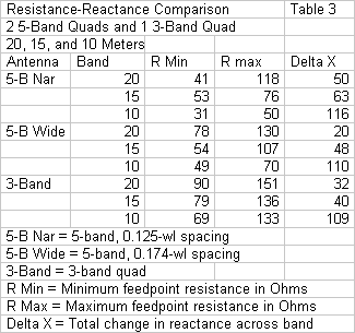
The first step is to compare the narrow and the wide 5-band quads. Since the frequency ratio between adjacent loops is the same for both beams, any differences are functions of the element spacing. The average differential in the feedpoint resistance between these two beams is 15 to 20 Ohms, with the higher average on 10 meters. Accompanying the lower feedpoint resistances for the narrow beam is a higher range of reactance values across each of the bands. Narrow element spacing therefore has an obvious negative impact on the ability of the array to cover all of each band. The 5-band arrays also show a systematic lowering of the feedpoint resistance as we increase the frequency band. The inner loops show a systematic lowering of the feedpoint resistance relative to more outward loops. Hence, when we combine this effect with the larger reactance excursion for the inner loops, we obtain large difficulties in covering 10 meters with narrow spacing.
The table allows us to make a second comparison, this time between the wide 5-band quad array and the tri-band design that we featured earlier. Note the descending values of feedpoint resistance for the 3-band model: about 90, 80, and 70 Ohms for 20, 15, and 10 meters, respectively. Every multi-band quad shows a reduction in the feedpoint resistance regardless of loop position in the presence of loops for other bands. The lower the frequency ratio between loops, the greater the reduction in feedpoint resistance. The tri-band quad uses frequency ratios between 1.34:1 and 1.5:1.
In contrast, the 5-band wide quad uses frequency ratios between bands that average about 1.2:1. As a result, even the 20-meter minimum feedpoint resistance is lower than for the tri-band beam: about 80 Ohms compared to the tri-band value of 90 Ohms. The impedance value declines more rapidly as we move up in the HF region. On 10 meters, the differential between tri-band and 5-band minimum feedpoint resistance values is double that of 20 meters: about 70 Ohms vs. abut 50 Ohms for the 5-band model. For reference, the reactance ranges for the wide 5-band model and the tri-band model are comparable. You may repeat the exercises that we just ran using the maximum resistance values, although the minimum values are perhaps more critical.
The net result is that, as we move up the bands of a 5-band 2-element quad array, the feedpoint resistance drops much more rapidly than it does for a tri-band array that omits 17 and 12 meters. On 10 meters, the low resistance accompanied by a wide reactance range results in matching difficulties that are difficult to overcome. In most cases, we must de-rate the 10 meter coverage and even then rely on line losses of the main feedline to achieve a 2:1 SWR across the smaller portion of 10 meters. The comparisons provided by the numbers in Table 3 provide a demonstration of a quite general phenomenon. Given pre-set upper and lower frequency limits, the more bands that we pack into a multi-band 2-element quad array, the lower the frequency ratio between adjacent loop sets. As we lower the frequency ratio, the feedpoint resistance drops more rapidly, even though the reactance range may not change very much. The higher the ratio between reactance and resistance, the more difficulties we encounter in effecting a match to a main feedline of a specified characteristic impedance, with or without matching devices or networks.
The tri-band quad begins with higher feedpoint resistance values on all band. Hence, we require some form of matching. A 75-Ohm (or similar) match-line that is 1/4 wavelength--or shorter as necessary--allows us to match the quad on each band to a 50-Ohm main feedline. As well, we may achieve full band coverage on all 3 bands with an SWR value of less than 2:1 (without relying upon losses in the main feedline). In a nutshell, this small demonstration shows why I chose to design a tri-band 2-element quad beam rather than stretch for a 5-band model that would fail to provide full-band coverage on 20 through 10 meters.
Conclusion
These notes have described and analyzed the structure and performance of a tri-band 2-element quad beam for the wider upper-HF amateur bands of 20 through 10 meters. The design rests upon wide-band monoband quad beams and adjusts the dimensions to obtain as close to monoband performance on each band as feasible. In fact, the beam comes very close to replicating monoband performance. The array allows us to match the individual feedpoints to a 50-Ohm main feedline by the use of 75-Ohm lines of prescribed lengths, some of which are less than the usual 1/4 wavelength. The array presumes the use of a remote switch or separate feedlines for each band. The structure uses spider construction to sustain the required spacing between the driver and the reflector on each band.
My choice of a tri-band quad array rather than a 5-band beam results from previous studies of what happens to the feedpoint resistance as we add bands and consequently reduce the frequency ratio between adjacent loops sets. The more bands that we add to a multi-band quad, the lower the ratio becomes. The result is both a general lowering of all feedpoint resistance values and a greater differential between the feedpoint resistance values for 20 and 10 meters. Since the reactance ranges tend not to change by any great amount, the high ratio of reactance to resistance tends to reduce matched coverage of 10 meters, regardless of whether or not we use a matching device or network. By sustaining a higher frequency ratio between adjacent loop sets in a tri-band model, we may overcome the matching issue.
All of these notes presume that the general parameters of quad operation over the wide amateur bands are acceptable. A 2-element quad shows good gain with the typical driver-reflector parasitic-assembly decrease in gain with increasing frequency. However, the 180-degree front-to-back ratio shows considerable variability, with a relatively high mid-band peak but band-edge values that are only somewhat higher than the ones that we obtain from a 2-element driver-reflector Yagi. Finally, full-band matching is achievable with an appropriate matching line, but only if we begin with a basic design optimized for wide band coverage.
Cubical Quad Notes Vol 1 - 3 available in PDF book format on the Books Page.
Updated 04-01-2007. © L. B. Cebik, W4RNL. This item appeared in AntenneX, March, 2007. Data may be used for personal purposes, but may not be reproduced for publication in print or any other medium without permission of the author.