 ANTENNAS FROM THE GROUND UP
Folks often forget that we do not need aluminum tubing to make a beam antenna. Wire will do, if we are content to point it in only one direction. For the lower HF bands, wire beams can be particularly useful for folks desiring more gain in front and less behind.
We shall look at two types of wire beams that operate fairly well at how antenna heights-- say 35' up at 40 meters. First is the standard parasitic reflector-driven element combination we call the 2-element Yagi. Second will be a somewhat more compact wire beam called the Moxon rectangle. Both use only about 1 wavelength of wire and may be worth considering.

The reflector is parasitic because it is not directly fed power. Rather, because of its length and distance from the driven element, the current on the wire is of a magnitude and phase to augment the radiation in the forward direction and to diminish it to the rear. Because the two elements are electrically interlocked, the elevation angle of maximum radiation tends to be lower than for a single wire antenna, such as a center-fed dipole.
Figure 2 shows the free-space azimuth pattern of a typical wire 2-element Yagi for 40 meters.

The Yagi gain can run up to about 6 dBi in free space, about 4 dB higher than a dipole in the same position. The front-to-back ratio for a 2-element Yagi will typically run 10 to 12 dB, about 2 S-units reduction in signal strength to the rear. Designing for an easy match will lower the above numbers a bit. Still, the forward lobe is relatively wide, and side rejection can be good.
For 40 and 30 meters, typical wire dimensions are the following:
Dimension               40 Meters   30 Meters

El. #1 (DE)             66'         46.6'
El #2 (Refl)            70'         49.4'
Spacing                 20'         14.1'
With these dimensions, the feedpoint impedance will be close to 50 Ohms and the 2:1 SWR bandwidth should cover most of the band. (Wire antennas will have somewhat narrower SWR bandwidths than antennas made from fatter tubing.).
One of the advantages of a wire Yagi is that it requires no more wire than a full-wave loop. Unlike vertically-oriented loops, both wires of the Yagi are at the maximum height available. Therefore, standard wire antenna construction can be used throughout. The 2- element Yagi is thus a very useful step on the road to even more complex antennas in the future.
Figure 3 and Figure 4 show the anticipated azimuth patterns of wire Yagis at antenna heights of 1/2 wl and 1/4 wl, respectively. In each case, although some of the side rejection is diminished, the antenna retains useful gain and front-to-back ratio. In addition, the elevation angle of maximum radiation is lower than a dipole at the same height.


Of course, wire Yagis are fixed-direction antennas. Hence, the builder must orient them in the direction most desired. In exchange for this limitations, the builder can save large amounts of money required for towers, rotators, and self-supporting aluminum antennas for the lower bands. Structural engineers may find the challenge of designing, erecting, and maintaining a rotatable beam for 40 and/or 30 meters a wonderful project. However, the average home builder will be able to build multiple Yagis for less than the cost of the rotator alone.
It is possible to build 3-element Yagis by adding directors to the assemblies noted here. However, at low heights typical of most backyards, the added complexities rarely add significant performance. The feedpoint impedance of 3-element beams tends to drop rapidly, making antenna matching more of a problem.
In the end, the 2-element Yagi is perhaps the most practical wire beam for most builders. Feeding it with parallel transmission line is feasible and may make the antenna usable as a single wire on higher HF bands.

A full analysis of the Moxon Rectangle appears in the Spring, 1995, issue of Communications Quarterly. The dimension given here, reproduced from an article I originally wrote for QRPp, have been adjusted to provide a match closer to 50 Ohm coax.
The Moxon rectangle is a wire antenna that can be fix-mounted or rotated. It is directional with almost the gain of a 2-element Yagi (5.8 dBi in free space) and has an outstanding front-to-back ratio (greater than 40 dB in free space), with a very broad frontal lobe (-3dB beamwidth = 70 degrees, usable beamwidth = nearly 180 degrees forward). The basic free space pattern of the Moxon is in Figure 6.

Table 1 provides dimensions for Moxon rectangles for 40 through 10 meters. The dimensions are not perfect simple scalings, because the length-to-wire-diameter ratio changes for each ham band.
Moxon Rectangle Dimensions for 40-10 Meters
Band        Freq.       A           B           C           D           E
10          28.50       12.44       1.94        0.41        2.41        4.76
12          24.94       14.22       2.22        0.46        2.76        5.44
15          21.20       16.72       2.63        0.52        3.25        6.40
17          18.12       19.56       3.10        0.59        3.80        7.49
20          14.17       25.00       4.00        0.72        4.85        9.57
30          10.12       35.00       5.60        1.00        6.80        13.40
40          7.15        49.56       8.01        1.33        9.63        18.97

Table 1.  Dimensions for Moxon Rectangles for 40 through 10 meters.  All models #14 copper
wire.  Dimensions are in feet, and frequencies are in MHz.
All of the antennas exhibit feedpoint impedances between about 56 and 58 Ohms, a close match to the standard amateur 50-Ohm coaxial cable. Free space gain and front-to-back ratio are consistent for all the models, averaging 5.8 dBi and greater than 32 dB in free space, respectively.
All of the models use #14 copper wire, although the various factors that contribute to the Moxon pattern tend to cancel out as wire size increases. Hence, tubing models will have dimensions close to those for the thin wire models. However, they will exhibit a broader SWR bandwidth.
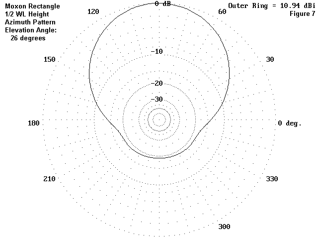
At heights below 1/2 wavelength, the front-to-back ratio will deteriorate somewhat, but usable values can be obtained. Figure 7 and Figure 8 respectively show the azimuth pattern of a Moxon rectangle at the elevation of maximum radiation, with a height of a half wave length and a quarter wave length above real, medium ground.

The bandwidth for 2:1 SWR is about 100 kHz on 40 meters, using #14 wire. Above 40 meters, the 2:1 SWR bandwidth covers the entire amateur band. For 30 and up, the front-to-back ratio is better than 15 dB across the band at heights of 35 feet and up. Many construction methods are possible, whether the material is wire or aluminum tubing. I shall leave the exact methods to the reader's ingenuity. For 40 and 30 meters, installation would likely be similar to the construction of any other fixed wire array. As with 2-element Yagis, it is possible to build separate antennas oriented in different directions. The only costs are for wire, insulators, rope, and feedline.
For 20 meters and up, it is possible to erect lightweight platforms of stressed PVC tubing and possible to rotate the entire antenna with a small TV rotator. Although I have not built concentric Moxon rectangles, a "Christmas-Tree" of Moxons is likely to be easier to tune. Separate feedlines for each band are desirable, as a common feed is likely to run into detuning effects, especially between 20 and 10 meters.
The standard of comparison for the Moxon is the 2-element Yagi. While a Yagi has marginally more gain, the Moxon's front-to-back ratio is very much superior. It will likely improve your ears much more than it will diminish your voice or yur key. And, as the old but true saying goes, if you can't hear 'em, you can't work 'em.
The basics of the Moxon rectangle appear in G6XN's HF Antennas for All Locations. The necessary information is scattered throughout the volume, which, unfortunately, is written in a somewhat difficult style. However, wading through the somewhat dense prose can be rewarding for the wealth of information there, along with some very strong opinions--not all of which are equally well founded. Moxonþs own antenna is a fixed rectangle with equal element lengths. He remotely loads them as needed to make a reversible beam. The design is derived from the VK2ABQ "button" beam, formed by splitting a horizontally oriented 1 wl loop on each side and inserting a small insulator or coat button. One element is fed; the other forms a modest reflector. From this humble beginning was born the more refined and optimized rectangle described in this installment.
The ZL Special: Two elements spaced approximately 1/8 wl and connected with a parallel transmission line about 45° (with a half twist) long form the classic ZL Special antenna, popular in the early days of post World War II beams. In those days, Yagi design among amateurs was a hit or miss affair, mostly miss, and performance was usually disappointing. The ZP Special seemed to rival 3-element beams of the time.
However, the ZL Special is a 2-element beam and cannot exceed in gain the limits for 2 elements. Original models with standard dipoles used 72 Ohm parallel transmitting transmission line for the phasing line. This line is almost impossible to come by these days (although a lighter lab signal line is available on occasion).
Roy Lewallen's Field Day Special is a version of the ZL Special using 300 Ohm feedline for both the elements and the phasing line. It makes a dandy Field Day antenna that rolls up in a compact ball for transport.
Quad Beams: Delta, square, and rectangular loops, vertically oriented but horizontally polarized, are popular antennas. Adding a second element, tuned to a frequency about 5% lower than the driven element, can transform any of these loops into a beam with performance capabilities similar to a 2-element wire Yagi. (These antennas for the lower HF bands are low in height and excess claims for gain and front-to-back ratio should be avoided.)
With loading stubs for the reflector and a switchable driven element, it should be possible to create a bidirectional beam. These antennas will not likely match coax, but parallel feedline for a beamþs driven element is perfectly good. You may even be able to use the array as a non-beam on other bands.
Updated 07-01-2000. © L. B. Cebik, W4RNL. Data may be used for personal purposes, but may not be reproduced for publication in print or any other medium without permission of the author.