One common problem faced by many of today's hams is a total lack of space for an antenna system. Sometimes land restrictions prevent construction of the ideal antenna farm. Sometimes family objections get in the way. Multi-family dwellings also defeat antenna farm dreams.
Suppose that you can put up only one antenna and that it must be vertical in order to use the minimum space possible. One common solution to the problem is to buy a trapped multi-band vertical and place it on the roof, with the minimum number of radials tacked down to the roofing shingles or draped over the eaves. Most of the available trapped monopoles are good antennas of their type, but they are initially costly.
Is there a cheaper alternative? In fact, there is a much cheaper alternative that is also less visible. However, there will be several kinds of work involved, and you will need an antenna tuner.
Although an antenna tuner (ATU) is part of any antenna system where it is used, I tend to separate the cost of the ATU from the cost of the antenna. In a lifetime, one will wear out many antennas, but a good tuner should last forever. So I shall assume that you have--or will obtain--the best ATU for your operating needs.
A 20-Meter Vertical Dipole
Any dipole, when placed horizontally over the ground, shows the familiar figure-8 pattern broadside to the wire, even if we change its length from about 3/8 wl to about 1 wl long. (The lower the antenna height, the more "thick-waisted" the pattern gets.) As we lengthen the wire, the beamwidth gets narrower while the peak gain gets a bit stronger.
If we turn the dipole to a vertical position and elevate it off the ground by a few feet, we obtain an omni-directional pattern quite similar to that of a standard ground-plane monopole. The same tendencies that kept our horizontal dipole showing its two lobes broadside to the wire now keep the elevation angle of radiation low as we change the length of the vertical dipole from 3/8 wl up to 1 wl long.
Now let's fix the length, using a standard 20-meter dipole as our vertical antenna. As shown in Fig. 1, we might place this antenna 10' (3 m) off the ground and support its upper end, which is now about 43.5' (13.25 m) off the ground.
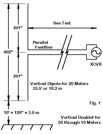
At this point, the only change from standard ham practice that we shall make is to substitute parallel feedline for our usual coax. Although this move will require a bit of special attention--to be discussed further on-- the basic run should be brought as straight away from the vertical as possible for as long as possible before routing it to the station. We shall use our ATU to provide a match between whatever impedance appears at the ATU and the station equipment.
Our 20-meter vertical dipole is nearly 3/8 wl long at 30 meters. It is 1 wl long on 10 meters. For the bands between 20 and 10, the antenna is somewhere between 1/2 and 1 wl long. It meets the conditions for having a decently low radiation angle on all of these bands.
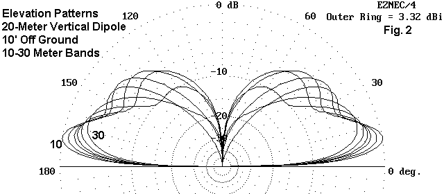
Fig. 2 shows the elevation patterns of our vertical dipole for all bands from 30 meters through 10 meters. As we expected, if we increase frequency, the main lobe gets a bit lower, ranging from 18 degrees on 30 to 10 degrees on 10. Of course, as we might also expect, the gain is much lower than that of a beam, but then, we are contemplating this antenna for locations where a beam is impossible anyway. The following table shows the modeled gain and elevation angle for a 1" diameter aluminum version of the antenna on each of the bands.
Band           Gain           Elevation Angle
30 meters      0.9 dBi        18 degrees
20             1.4            15
17             1.8            13
15             2.1            12
12             2.7            11
10             3.3            10
Even wire versions of the antenna (#12-#14 AWG) will show almost identical gain and elevation figures.
Construction
Since we are not seeking an exact match to a 50-Ohm coaxial cable, the dimensions of the 20-meter vertical dipole shown in Fig. 1 are not at all critical within a few inches or centimeters. The antenna can be wire or tubing, depending on what the available support systems will allow.
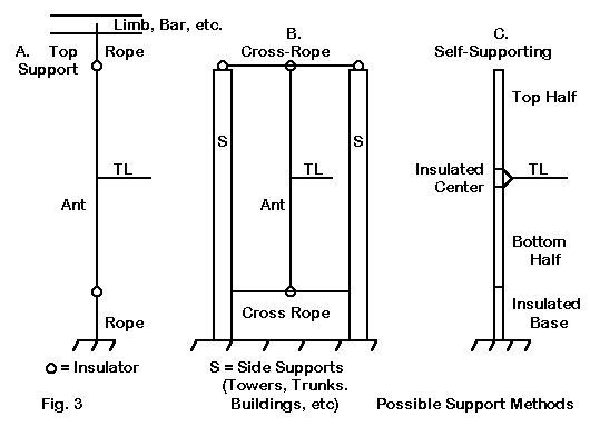
Three of many possible support systems appear in Fig. 3. On overhead limb of a tall tree can support the wire antenna, with a rope holding the bottom end in place. If the transmission line is very securely attached to the wire, a little tension will keep the vertical from flapping in the breeze. If you have 2 support structures separated by a space, you can support the top and bottom of the antenna with cross ropes. Of course, you can also mix and match the two top and bottom support means shown in the sketch.
Equally effective will be a self-supporting version of the antenna, although developing a 10' support may be more difficult. As well, the antenna--if made from standard tubing--may wave mightily in stiff breezes unless guyed with light ropes about 2/3 the way up the tubing.
It is impossible to analyze in the abstract all of the difficulties that may be faced by individuals trying to get an antenna in place in very restricted spaces. So the best advice is to give your situation careful study, looking for support possibilities in everything you see. For example, if the roof or chimney top is not quite high enough, but a tree in the area is more than tall enough, you can use a sloping rope to connect the two and support the wire antenna.
There is no magic about the 10' minimum height selected for this antenna. Safety is the foremost concern. The end of the antenna on some bands will carry a very high voltage that can create RF burns if someone touches it while you are transmitting. Although the top height provides good performance, you can lower it if you bend the bottom wire to the side at a safe distance above everyone's head. The change in performance is small enough that it is unlikely to be noticed.
Matching the Antenna to the Station Equipment
The impedance that your ATU sees at its terminals depends on several factors:
Let's take up the first two considerations together. The impedance of the antenna at its center feedpoint will change from band to band. From any given impedance at the antenna terminals, the impedance will vary along the feedline depending on the characteristic impedance of the line, the line length, and the velocity factor of the line. 300-Ohm twinlead has a velocity factor of about 0.8 due to the solid vinyl insulation between wires. Almost all other parallel lines have velocity factors above 0.95, and home-made line with periodic spacers has a velocity factor of just about 1.0.
Impedance, recorded as resistance and reactance in series, repeats itself every electrical half wavelength (taking into account the velocity factor) along a transmission line. As a test, I modeled the antenna with various physical feedline lengths, using a 3" spacing between #12 wires to simulate a home-made line. With lengths of 1/8, 1/4, 3/8, and 3/4 wl of transmission line at 20 meters, I obtained the following impedances.
                    Transmission line length at 20 Meters
Band Antenna        1/8 wl         1/4 wl         3/8 wl         1/2 wl
30     35 - j 465**   20 - j  95     25 + j 225     60 + j 175   4250 - j6720*
20     70 - j  30    120 + j 450   2880 + j1950*   170 - j 625     74 - j  50
17    165 + j 420   1950 - j1310*   125 - j 235    155 + j 360   2740 - j 465*
15    340 + j 830    235 - j 650    105 + j 150   2215 + j 135*   130 - j 305
12   1310 + j1720*    90 - j 200    300 + j 870    135 - j 440    135 + j 440
10   4200 + j 110*    65 + j   5   4300 - j 175*    70 + j  10   4250 + j 105*
The repetition points will vary from band to band, since they occur as a function of wavelength. Within in the limits of this small test, I have flagged very high impedance values that might exceed the range of the tuner controls to match easily. Notice that as the line length changes, the values appear on different bands. Hence, for any given line length, only 1 or 2 of the bands are likely to present a difficult matching situation.
The double-star entry shows a potential weakness of the system on 30 meters. The very high ratio of reactance to resistance, along with the low resistive component, indicates a very high SWR on high-impedance transmission lines, and even these lines will show significant losses under these conditions. As well, note the very slow change of impedance and the sudden spike in values as we change the length of the transmission line. Hence, finding a set of values at which the tuner can provide a satisfactory match at low losses may also be difficult.
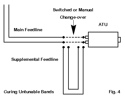
The solution is sketched in Fig. 4. Adding a 6-10' (2-3 m) length of line- -either manually or with a knife switch--will under most circumstances change the impedance values enough on a troublesome band to let you obtain a desired match. The extra line should form a wide loop and not be folded back on itself too tightly.
The third circumstance which can alter the impedance that appears at the tuner terminals is the degree to which the transmission line is coupled to the antenna field. This can occur whenever the line forms an angle other than 90 degrees with the vertical antenna wire. The closer to the antenna that the angled transmission line is, the stronger the coupling. Antenna field coupling to the transmission line appears as common mode currents-- that is, currents that are the same in magnitude and phase on both wires. These currents add and subtract from the normally equal magnitude but opposite phase currents on a transmission line, upsetting the desired balance. The currents also show up in the shack as RF that can disrupt equipment operation or give minor RF shocks at any metal corner. They may also cause RF interference with household devices. Ordinarily, they are not strong enough to reradiate in ways that seriously disrupt the antenna pattern itself.
The cures require a little work. First, re-examine the transmission line routing to see if the right angle to the antenna can be maintained farther away from the antenna wire. Second, you may install a 1:1 balun at the entry point to the house and use coax from that point to the ATU--if the ATU is a network-type tuner. (This treatment is not needed with a link tuner if the input and output sides do not have a common ground path.) If the coax run is short enough, losses due to high SWR will not be great. A ground wire--as short as possible--to a good earth ground should go from the balun end of the coax. Third, you may also install a balun at the input end of the ATU or use brute-force ferrite split blocks over the coax on the input side of the ATU (and on the output side, if using the second suggested system).
The suggested routes of cure are given in the recommended order of implementation. Only the most stubborn cases require all three techniques. The exercise will teach you much about how RF gets from an antenna into the shack--and how to block it most effectively. The presence of common mode currents does not mean that the antenna is not performing correctly or that the pattern shape and strength are ruined. It only takes a little RF in the shack to disrupt matters.
One question that often crops up with multiband antennas is whether one might use coax instead of parallel line all the way from the antenna to the ATU. If the coax run is very short, one might use this technique of feeding the vertical doublet, but some of the impedances at the antenna terminals will present a very high SWR to a 50-Ohm coaxial line. As frequency increases, so to do coax losses, and performance on the highest bands may suffer from appreciable power being turned into heat in the line. For this type of application, parallel feeders are far more efficient.
How "Good" is the Multiband Vertical Doublet
When a dipole is pressed into service on bands other than the one for which it is near resonance, it often becomes other than a dipole. The old name "doublet" is more properly used with such antennas. In assessing how good such an antenna is, of course, we must compare it to the right group of antennas. Comparing it to a beam is unreasonable, since we already agreed that the antenna is for use where no beam is feasible.
A fairer comparison is with a 20-meter ground plane monopole elevated to about the same top height as the vertical doublet. This antenna represents a roof top mounting, such as one might use with a trap monopole. For this test, the ground radials of the monopole were sloped, as they might be on a rooftop, and the antenna was resonated to give a 50-Ohm resistive impedance on 20 meters.
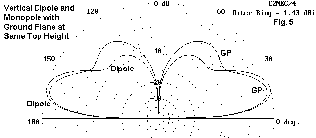
Fig. 5 compares the 20-meter elevation patterns of both the vertical doublet and the monoband monopole with a sloping ground plane. Although there are slight differences in the two patterns, performance of the two antennas is close enough that the user would detect no operational differences.
If you have the space and resources for a better antenna, by all means use it. However, for the ham with limited space and resources, a vertical doublet for 30 through 10 meters--based on the 20-meter dipole--makes an effective antenna for general communications.