We have in past episodes discussed the ground calculation systems associated with the most common antenna modeling cores, MININEC and NEC. A development in one of the commercial MININEC packages (Antenna Model) brings those ground calculation systems back into focus.
The Basic or Native Ground Calculation Systems
The MININEC ground calculation system is perhaps the most rudimentary, since its development paralleled the original intent of MININEC: to offer reasonably accurate round-wire antenna modeling in a Basic package that would run on early PCs with very limited RAM and disk storage. Over the years, the latest public domain version of MININEC (3.13) has undergone various degrees of modification to achieve two major goals. One aim of redevelopment was to extend the 128-segment and later 256-segment limit for models. Conversion of the package to a Windows format and a compatible programming code system has yielded MININEC versions with almost unlimited segments, although almost all such packages make their core runs more slowly than the compiled FORTRAN that is common to most NEC packages. The second goal was to correct some of the modeling weaknesses that included an error that increased with frequency, problems with very close-spaced wires, and potential errors associated with angular structures. Various software packages have addressed individual limitations, but Antenna Model has achieved the most thorough set of correctives.
Perhaps the one enduring feature of MININEC that resisted alteration for the longest period is the ground calculation system. As far back as 1991, Roy Lewallen, W7EL (author of ELNEC and EZNEC programs) provided careful warnings about the use of the MININEC ground calculation systems with horizontal wires closer to ground than about 0.2 wavelength. (See "MININEC: The Other Edge of the Sword," QST, Feb., 1991.) Since then, warnings have emerged concerning errors ranging from small to large with sloping wire constructs where one end is at ground or close to ground. These constructs have a horizontal component and to that degree suffer the MININEC ground calculation limitation. Vertical wires do not have the same limitation as horizontal wires. When a vertical wire touches the ground, it will return a plausible antenna pattern and gain report. However, the source impedance does not change with changes in the assigned ground quality. Rather, MININEC always returns the source impedance over perfect ground. Hence, it is not possible to track variations of source impedance due to ground losses with the MININEC native ground calculation system. If the modeler constructs radials, then all wires must be above ground, and the radials are subject to the horizontal-wire limitation that we have already noted.
NEC (both -2 and -4) offer two real-ground calculation systems. The use of 2 separate systems results again from the early days of slower computers. The Reflection Coefficient Approximation (RCA) system produces faster core run times, but it suffers from a minimum height restriction for horizontal wires. Various sources give different values for the recommended minimum height above ground, ranging from 0.1 to 0.2 wavelength. The error introduced into horizontal wires below the recommended limit does not follow the same trends as MININEC ground calculation errors under the same circumstances. Vertical wires touching the ground also produce errors. However, NEC's RCA system does have a mode of operation that simulates ground radial systems using the number of radials and radial length specified by the user. It is available only in packages that make the full set of NEC commands available. Like the MININEC ground calculation system, the RCA system in the radial mode produces plausible patterns and gain reports. However, it responds to differences in the ground quality and the number and length of radials. Still, in this mode of operation, the RCA system returns source impedance reports based on perfect-ground or image calculations.
The second NEC ground calculation system is usually called the Sommerfeld-Norton (S-N) system. It runs more slowly than the RCA system, but that factor has largely become a superfluous concern with the speed of modern PCs. With respect to horizontal wires, the S-N ground calculation system provides accurate gain and source impedance reports with wires very close to ground. If h is the height above ground in wavelengths and a is the wire diameter in wavelengths, then the closest approach to ground for a wire (in wavelengths) should be as follows:
With respect to vertical wires, the S-N ground calculation system suffers the same limitation as the RCA system. Vertical wires touching the ground will yield erroneous results. As a result, models dealing with vertical monopoles and arrays based upon them must construct radial systems in accord with other limitations of their NEC core. For NEC-2, all wires must be above ground, although with the S-N ground calculation system, the vertical and radial wires may approach the ground in accord with the recommended equation. In NEC-4, we may model buried radials. Radials may converge below ground or may have sloping sections that converge above ground. In either case, a wire that passes Z=0 may do so only at a segment or a wire junction.
Packaged Ground Calculation Systems
Most antenna modeling packages provide the user with the ground calculation systems native to the core used in the package. MININEC packages provide the user with the MININEC ground. NEC-2 and NEC-4 packages make the S-N and RCA ground calculation systems available. However, there are 2 known exceptions to this general trend.
EZNEC (in all its version-4 forms: regular, Plus, and Pro) gives the user a choice between the S-N and the MININEC ground systems with either the NEC-2 or NEC-4 cores. The premises behind this set of options are straightforward. First, modern PCs do not need the speed advantage that was once a main reason for using the RCA system. The time saved between ground calculation systems at the original PC CPU speed of 2 MHz was significant, but almost undetectable with current 2 GHz CPUs. S-N system calculations can still be saved to a file to free the RAM in successive runs for mutual impedance and currents calculations, but current RAM capabilities have largely obviated the need for this step. Therefore, for all antenna models with horizontal components, the S-N ground calculation system's greater accuracy dictates its use.
Second, there are still a number of modeling applications in which the user will wish to connect a vertical wire directly to ground without employing a radial system. Preliminary performance comparisons of various sorts become highly efficient using this technique. However, neither the S-N nor the RCA systems return plausible results in NEC using this technique, especially with respect to the source impedance. Although less than perfect relative to models using buried radial systems in NEC-4 plus the S-N system, a MININEC ground provides quite reasonable values for initial comparisons, along with the source impedance that applies to the use of a perfect ground.
There is a qualification that we must note on this account. The RCA system, when set up for buried radials, would offer the advantages for initial comparisons with a MININEC ground, with the added advantage of showing some sensitivity to the conditions of the radial field. However, the set-up for this option involves a somewhat interesting relationship between the ground specifications command and the pattern request command. The ground specification command is divided between 2 possible commands, GN and GD.
If the GN command's I2 (NRADL) entry is greater than zero, then you must use the GD command to enter a second medium. If NRADL is 1 or more, then the meanings of F3 through F6 change from a more basic set-up of the command. Let's see what happens to the GN command under these conditions.
Cmd   I1     I2     I3   I4   F1    F2    F3    F4    F5    F6
      IPERF  NRADL  0    0    EPSR  SIG   RADS  RADW  --    --
GN    0      8      0    0    13    .005  .237  .001
I2 shows a request for 8 radials. The single-medium ground quality values go into F1 and F2 as always. However, F3 and F4 have new meanings. RADS is the radius of the screen, or the length of the individual radials in the screen. RADW indicates the radius of the individual wires composing the set of radials. Both values are in meters.
In NEC-2, the RP command must have an I1 assignment of 4 for a simple set of radials. If there are GN and GD commands requesting both a screen and a second medium, then the NEC-2 RP command must let I1 = 5 for a screen and a linear cliff or let I1 = 6 for a screen and a circular cliff. NEC-4 uses I1 = 0 in the RP command for all these cases, since the type of cliff will be set in the GD command. NEC-4 will read a NEC-2 model with only a screen request by treating the RP4 request as RP0.
The radial screen option in the GN command applies only to the RCA real ground type (I1 = 0) and is not allowable with a request for an SN ground (I1 = 2). The calculations are based upon a modified reflection coefficient, and the resulting source impedance report will be the same as for a perfectly conducting ground (I1 = 1). Despite this limitation, the system is more versatile than simpler ground systems (such as those used with MININEC cores), since it will show differences in far-field patterns due to changes in the ground quality and changes in the number of radials.
As currently implemented, EZNEC has no provision for setting the RP pattern request command to the values required by the RCA ground radial set-up. Hence, the facility that the program makes available for verticals without modeled wires for a radial system is the MININEC ground. Packages that make the complete set of NEC-2 or NEC-4 commands available to the user may substitute the RCA ground radial set-up for the MININEC ground calculation system for initial comparisons of vertical antennas and arrays.
Special Note: As with all comments on the current capabilities of an existing program, the notes are believed to be accurate as of the time of writing. However, software developers tend to continuously upgrade and modify their offerings. Hence, what is true at the time of writing may prove to be outdated by the time of publication.
The second package to provide the user with non-standard ground calculating systems is a version of MININEC: Antenna Model. We have noted on more than one occasion that this package provides the most thorough set of correctives to the shortcomings of the raw MININEC version 3.13. As noted in previous columns, for comparable models, Antenna Model's MININEC core tracks very well with NEC-4. As well, MININEC offers the added advantage of showing no limitations wherever we have junctions (angular or linear) of wires having different diameters. However, like other MININEC offerings, Antenna Model lacks some features that are standard in NEC, such as the TL transmission-line and the NT network facilities.
Antenna Model shared one limitation with all versions of MININEC: the use of the MININEC ground calculation system. However, the software developers found a way the graft both the RCA and the S-N ground calculation systems to their MININEC package. Hence, with two qualifications, Antenna Model offers the same ground calculation advantages as NEC. The first qualification is that MININEC is like NEC-2 in that all wires must be above ground level. Second, MININEC offers no provision for setting up the complex interaction of commands that allows the RCA ground calculating system to add radials. Hence, the chief benefit of the addition of NEC ground calculating systems to the Antenna Model MININEC package lies in the realm of an improved ability to handle horizontal or slanted wires close to the ground. For example, Antenna Model is the only MININEC offering that is capable of producing accurate models of NVIS antennas that ordinarily have one or more wires within 0.2 wavelength of the ground.
Some Comparisons
Whenever we encounter a new modeling program feature, we should make a set of test runs in order to establish whether or not the claimed specifications of the feature are as accurate as we need for our work. The exact dividing line between acceptable and unacceptable will, of course, vary with the specifications for the modeling work that we do.
Since the addition of the NEC ground calculating systems to MININEC in Antenna Model benefit low-lying horizontal wires the most, I set up a series of small tests, of which the following one is an example. I created a simple dipole for 29.97925 MHz, where a wavelength is exactly 10 meters. I used 31 segments for a NEC-4 model and 30 segments for the corresponding MININEC model. The dipole used a perfect or lossless wire with a diameter of 1 mm. With a length of 0.485 wavelength (4.85 meters), the model produced resonant dipoles in free space on both NEC-4 and MININEC. Resonance here means a remnant reactance of under +/-j 1.0 Ohm. The source impedance in NEC-4 was 71.99 - j0.43 Ohms, while in Antenna Model's MININEC, the source impedance was 71.84 -j0.56 Ohms. The differences fall well within what we would expect with a simple 1-segment change in segment density. The change, of course, reflects the difference in the position of the source relative to the segments themselves (MININEC at a junction, NEC within a segment). In both cases, the free-space gain was 2.14 dBi.
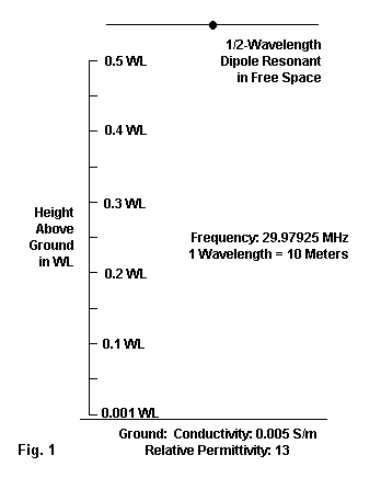
With this model, I then created all of the ground calculation system variation that I might compare, using the so-called "standard" or "average" ground quality: conductivity: 0.005 S/m, relative permittivity: 13. I then set the dipole at a series of heights, beginning at 0.5 wavelength above ground. Each successive step brought the antenna 0.05 wavelength closer to ground down to a height of 0.05 wavelength. To simulate the closest approach to ground permissible, I set the final step at 0.001 wavelength above ground. The values for this height appear in the tables, but not in the graphs, since the increment is not linear and since some of the values would have obscured variations among the other steps in the sequence. Fig. 1 outlines the test set-up.
The first test directly compared the Antenna Model MININEC use of the S-N system against the NEC-4 version of the antenna. The NEC-4 test employed EZNEC Pro/4, but there is no detectable difference among the core outputs of NEC-4 offerings. Indeed, running the same NEC-4 compiled Fortran core on different CPUs and operating systems generally shows a wider variation in results than running two different NEC-4 cores on the same CPU and operating system.

Table 1 shows the results of the test. From 0.5 wavelength down to 0.05 wavelength, the correlation of results is as exact as we may expect from models with slightly different segmentation densities. The only variant result is the source impedance at a height of 0.001 wavelength (1 cm). Antenna Model certifies its results only to 0.01 wavelength, although the variance in source impedance is only about 7% at 1/10 the minimum recommended height of use. For all practical cases, Antenna Model's MININEC with the S-N ground is the equal of NEC's results with the S-N ground calculating system.

Since Antenna Model also implements the NEC RCA ground calculation system, we might as well perform the same set of modeling steps using it. However, we cannot find our NEC-4 counterpart models in EZNEC. So this set of models uses NSI's GNEC. See Table 2. Note that the correlations between both the gain and the impedance reports are quite tight down to a height of about 0.2 wavelength. Then we see a drifting apart of values that becomes more extreme from 0.1 wavelength down to the minimum height. For reasons that we shall see shortly, it is unlikely that we would uses this ground below 0.2 wavelength for horizontal wires, so the divergence of reported values between the NEC-4 and the MININEC cores is more artifactual than significant.

We can find the MININEC ground calculation system both in the MININEC-based Antenna Model and in the NEC-4-based EZNEC Pro/4. Therefore, we might as well complete the picture by comparing the reports for the same set of models using what most experts consider to be the least adequate system for horizontal wires. In fact, as shown in Table 3, the two cores yield as close to identical results as we can expect from the models involved, given the slight difference in segment density. The numerical differences between the MININEC ground results and the RCA ground results suggest that, while both use reflection coefficient approximations, they do not operate in exactly the same manner. The fact that the MININEC ground yields the same results whether attached to NEC-4 or to MININEC, while the RCA ground does not, is another indicator of differences between the two fast-running ground calculation systems.
There are alternative ways of viewing the same data. For example, we can compare in NEC-4 the reported gain values for both the S-N and RCA ground calculation systems. Fig. 2 connects the data dots, omitting the values for a height of 0.001 wavelength.
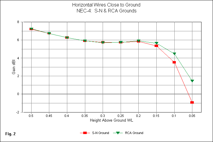
The chart shows that below 0.2 wavelength, the RCA system supplies gradually inflated gain values for the horizontal wire gain values. This is the same height at which we found some divergence between the NEC-4 and MININEC reported gain values and represents a rough limit for the reliability of the RCA system. Fig. 3 shows the corresponding source resistance information over the same range of wire heights.
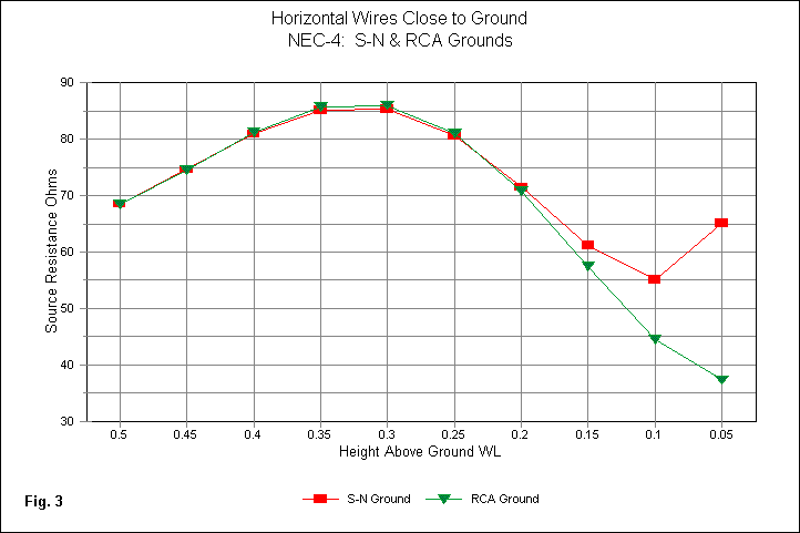
At 0.2 wavelength wire height, we find the same divergence of S-N and RCA values. However, there is a fair tracking down to 0.1 wavelength. At that point, the RCA source impedance reports continue downward, while the S-N values turn upward. This divergence has caused some users to consider 0.1 wavelength to be the minimum usable height for RCA ground calculation system results. However, if you examine Table 1 and Table 2. you will see that the NEC-4 reports for the lowest height show a lower source resistance for the RCA system than for the S-N system. The indication is that the turn upward in source resistance occurs at a lower height in the RCA system than in the S-N system. The net result is that the safest position at which to limit the use of the RCA system with horizontal wires is about 0.2 wavelength above ground.
Since 2 out of the 3 ground systems available in the Antenna Model implementation of MININEC are "imports," we might as well include all three systems in graphing the gain and source resistance reports. Fig. 4 compares the three reported values drawn from the right-hand columns of the 3 tables. Once more, I have omitted the lowest height, since it is not a linear increment and because its values would obscure changes in other values in the graph.
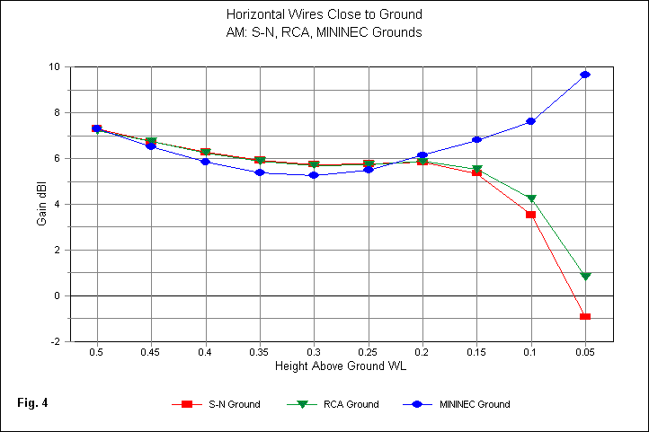
The S-N and RCA lines track well down to a height of 0.2 wavelength. The RCA terminal value at 0.05 wavelength is lower than for its counterpart using NEC-4, as shown in Table 2. However, the split from the S-N reported value sets 0.2 wavelength as a practical limit for using the RCA value. The major surprise may lie in the comparison of the S-N and RCA curves on the one hand and the MININEC ground curve on the other--throughout the complete range of values. Except for a coincidence of gain report at 0.5 wavelength, the MININEC ground curve diverges from the two other curves all along the range of heights, describing a shallow parabola. The coincidence of values near 0.2 wavelength is mostly coincidental, since the upward progression at heights below that level is a simple continuation of the questionable curve across its entire range from 0.5 wavelength downward.
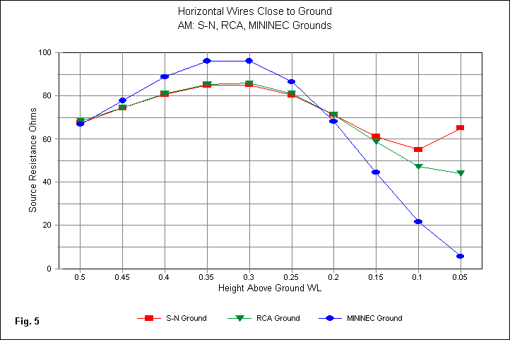
The graph of source resistance values in Fig. 5 shows a similar curve, but reversed. The inflation or deflation of source resistance values, relative to the S-N and RCA curves, is inversely proportional to the gain divergence. Hence, the MININEC ground system reports the highest gain values with the lowest source resistance values. In the end, for horizontal wires below 0.5 wavelength, the MININEC curves suggest that the formulation of the ground calculation was likely crude, over-simplified, or hasty, if not some combination of all three. That Antenna Model has grafted the S-N and RCA systems to its implementation of MININEC (especially when combined with its extensive correctives for most of the other MININEC weaknesses) provides the user with more assured results for any antenna structure having horizontal wires below 0.5 wavelength. The only redeeming function of the MININEC ground system is its ability to handle vertical antennas and arrays without demanding a radial system for at least initial comparisons. However, implementing the RCA radial command would allow the removal of the MININEC system altogether. This last remark, of course, is made with total ignorance of the programming difficulties that might be involved.
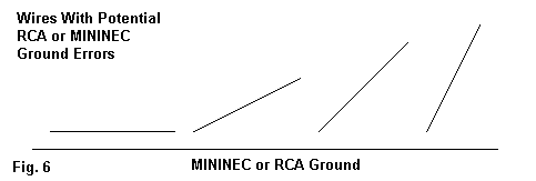
As a final reminder, we might also attend to Fig. 6. Each of the sloping wires has a horizontal as well as a vertical component. Hence, using either the MININEC or the RCA ground calculation systems, we shall encounter errors in both the gain and source impedance reports when part or all of the structure is below 0.2 wavelength. The error will be proportional to a. the amount of the wire that is below 0.2 wavelength and b. the relative preponderance of the horizontal component relative to the vertical component. This factor is often ignored by modelers of complex vertical arrays that may use sloping (guy) wires as active elements, whether directly or parasitically excited. Ignoring this situation imperils accuracy of the results.
MININEC is still widely used by numerous antenna modelers, especially since very cheap or free software using the core is readily available. However, not all public-domain MININEC implementations are equal. Indeed, the extensive modifications of the core--and now the ground calculating system--within Antenna Model almost remove it from the realm of MININECs except as a record of its genetic heritage.
Of course, Antenna Model is limited in the same manner as NEC-2: all wires must be above ground. For the most accurate round-wire modeling of arrays using buried radials, NEC-4 remains the core of choice. Nevertheless, the addition of the S-N and RCA ground systems within Antenna Model has given us a good occasion on which to compare low horizontal wire results for all of the extant ground calculation systems. Those comparisons are the main focus of these notes.