The terminated rhombic beam holds the position of king among all long-wire arrays. It is an extension of basic long-wire technology, a small piece of which we sampled in the preceding episode. Initially developed by Edmond Bruce in the early 1930s, the antenna served point-to-point communications needs well into the 1960s. During the 4-decade heyday of the rhombic, amateurs dreamed of having one of these high-gain, narrow-beamwidth, broad-band antennas--and of the acreage necessary to hold it. One humorist reported that his ideal antenna would be a very large rhombic located on a rotatable island in the Caribbean.
These notes are not aimed at evaluating the relative merits of the terminated rhombic. Instead, the goal is to address some questions that may arise in the course of modeling rhombic antennas of various types. Perhaps the simplest rhombic model appears in Fig. 1. The legs are 4 wavelengths each, which results in the specified dimensions. I selected the angle (alpha) between the centerline and each leg to yield the maximum gain for this model, which happens to be at a 3.5-MHz test frequency. The lossless model wires are 0.16" in diameter.
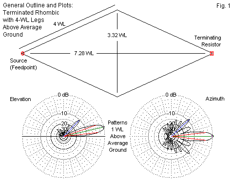
The patterns below the model outline show the reported elevation and azimuth plots for the modest rhombic. One main reason for the commercial use of the rhombic was the very narrow beamwidth as well as the high gain. However, the relatively strong sidelobes remained a concern for rhombic designers into the 1960s. The last major rhombic development was the dual offset rhombic design of Edmund Laport.
The following abbreviated list of references will provide more information on rhombics for those intrigued by long-wire technology. For a systematic treatment from a modeling perspective, see Long-Wire Notes, available from antenneX.
Bruce E., "Developments in Short-Wave Directive Antennas," Proceedings of the IRE, August, 1931, Volume 19, Number 8: the introduction of the terminated inverted V and diamond (rhombic) antennas.
Bruce E., Beck A.C., and Lowry L.R., "Horizontal Rhombic Antennas," Proceedings of the IRE, January, 1935, Volume 23, Number 1: the classic treatment of rhombic design, repeated in many text books.
Graham, R. C, "Long-Wire Directive Antennas," QST, May, 1937: an excellent summary of long-wire technology to the date of publication.
Harper, A. E., Rhombic Antenna Design (1941): a fundamental text on rhombics, based on engineering experience, with tables and nomographs as design aids.
Johnson, R. C. (Ed.), Antenna Engineering Handbook, 3rd. Ed., Chapter 11, "Long-Wire Antennas" by Laport.
Laport E. A., and Veldhuis, A. C., "Improved Antennas of the Rhombic Class," RCA Review, March, 1960, Volume XXI, Number 1: the introduction of the off-set dual rhombic.
Multi-Modeling Potentials
The model that produced the sample plots in Fig. 1 provides general guidance, but not refined analysis suitable for use as a final pre-building design. Besides lacking the environmental inputs relevant to a prospective building site, there are some fundamental modeling issues that preclude the use of this model as a precision replication of some particular rhombic or other long-wire array. First, the model uses one of several possible input configurations possible in NEC. Each configuration has its own strengths and weaknesses relative the NEC calculations. Second, the model uses a somewhat minimal segmentation density at 20 segments per wavelength.

Fig. 2 shows the pointed-end configuration used for the sample model. L is the leg length and is the square root of the sum of the squares of dimensions A and B. One advantage of this model is that it replicates angle alpha accurately. However, it does require the use of split sources and loads. An alternative configuration that we shall have to use shortly is on the right. The model places a single source and a single load on short end wires that create a blunt-end rhombic. The dashed line shows the virtual leg that has length L. However, the actual leg length is L' + C. As well, the wire labeled L' has a shallower angle relative to the junction with C than given by alpha. If we make dimensions A and B the same as for the configuration on the left, then we have slightly distorted the rhombic shape. The degree of distortion is a function of 2 factors: the length of C and the leg length L. If C is very short and L is very long, then the distortion will be small relative to the pointed-end model.
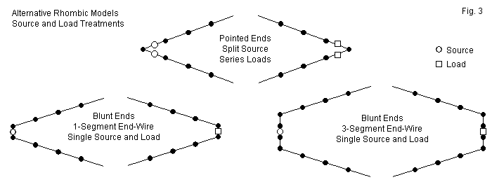
Fig. 3 illustrates the source and load treatments that accompany the two general configurations. Assume that all segments or distances between dots on the sketch have the same length. The pointed-end model places source excitation on the left-most segments of each of the two wires forming the feedpoint end of the rhombic. These sources are in series, and the net impedance of the source is the simple sum of the resistive and reactive components of each source. If we increase the segmentation density of the model, then the sources move closer to the actual tip of the rhombic. A similar condition applies to the series loads placed on the right-most segments of each wire approaching the termination end of the rhombic. The net resistive load is the sum of the two resistances, but if we increase segmentation density, the loads move closer to the actual tip of the rhombic.
The lower sections of the sketch show alternative methods of placing sources and loads at the furthest extremes of the rhombic. The method on the left uses a single segment wire for the source and another for the load. If we carefully size the 1-segment wires so that their length just about equals the length of each segment, NEC should yield accurate results, although it is preferable to have equal-length segments in a line on each side of the source segment. The lower right sketch shows a 3-segment wire at each end of the rhombic that achieves this goal. However, even with careful sizing of the wire length to equalize segment lengths throughout the model, the 3-segment wires increase the distortion of the rhombic shape relative to either the pointed-end or the 1-segment blunt-end versions.
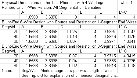
The amount of distortion in the rhombic shape is not large, even with a 3-segment wire at each end. Table 1 provides information on the dimensions of a test rhombic using 4 wavelength legs and an alpha angle of 24.5°, the angle needed to optimize for maximum gain in the original pointed-end model. The table shows the dimensions for all three versions, including the changing value of C as the segments in the main legs (L') grow shorter with increasing segmentation density. The worst case of distortion occurs with a segmentation density of 20 segments per wavelength while using a pair of 3-segment end wires. For 20 segments per wavelength, the end wires have individual lengths of 0.14 wavelength (or C = 0.07 wavelength). The distortion amounts to adding about 4% to each leg wire overall, although the angular portion of the wire is under 4 wavelengths. Nonetheless, the combination of configuration, source, and load changes can affect the modeling outputs.
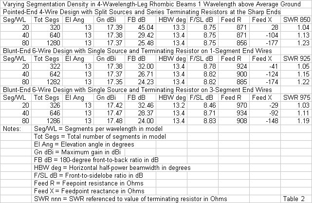
Table 2 provides the results of running all models under identical environmental conditions by placing each rhombic 1 wavelength over average ground at the test frequency. We need to scan the table in several different ways. First, if we compare the 3 models regardless of segmentation, we note that the terminating resistor increases value as we add the blunt end wires and increase their length. The terminating resistor was set with a segmentation of 20 segments per wavelength and remains unchanged as we increase the segmentation density for each model. The SWR reference impedance is also the resistance of the termination. For each model, as we increase the segmentation density, the feedpoint reactance grows more capacitive, and the feedpoint resistance decreases. The change in reactance is more radical than the decrease in resistance. However, reducing the terminating resistance in each model for a better match with the feedpoint impedance for a given segmentation density will also reduce the magnitude of the reactance.
Second, we can scan each model's table for other trends occasioned by increasing the number of segments per wire. The most dramatic case is the 180° front-to-back ratio, which is also a measure of the relative size of the lobe projecting directly rearward along the rhombic centerline. In all cases, it decreases as we increase the segmentation density, leveling off in the 24-25-dB region for all three models with 80 segments per wavelength. The beamwidth is stable for all models. So too is the front-to-sidelobe ratio, although the 3-segment end-wire model shows the greatest internal variation with changes in segmentation density.
With respect to the reported forward gain, the pointed-end and 1-segment blunt-end models show the closest coincidence in two respects. First, the gain levels closely match at all levels of segmentation, as do most of the other data related to radiation patterns. Second, both models show a slowly decreasing gain value as the segmentation density increases. In contrast, the blunt-end model using 3 segments in each cross wire shows an initially higher gain value, and that value continues to increase with the segmentation density.
The relatively close values that we find in Table 2 with respect to the performance of the pointed-end and blunt-end arrays, when each uses an optimized terminating resistor, can hide some differences. To show one of the differences, I varied the value of the terminating resistor across a wide set of values. The data in Table 3 selects 3 values that surround the final value and suffices to reveal the critical differences in model performance.
The data columns related to the radiation patterns reveal a consistent set of curves. The gain shows almost no change, with a slight numerical increase as the value of the terminating resistor increases. The front-to-side ratio also increases with the value of the terminating resistor. The front-to-back ratio peaks at mid-range, a characteristic of rhombics as the terminating resistor approaches its optimal value. In these respects, the two models are fully consistent. Since the terminating resistor values are not too far apart, even the feedpoint resistance values are not distant from each other.
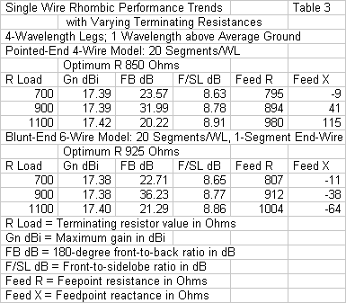
The key difference between the progression of values lies in the reactance column. The pointed-end model shows a reactance that becomes more inductive as the value of the terminating resistor increases. In contrast, the blunt-end model, even though it uses only 1 segment on the short end wire, shows a reactance that becomes more capacitive as the value of the terminating resistor increases. Older literature from the 1940s suggests that the rhombic builder should use a set of perhaps 3 to 4 resistors in series rather than a single terminating resistor. The goal is to reduce the capacitance across the total termination by creating several capacitors in series. If the models reflect reality (a major presumption in the absence of a physical test rhombic), then the reactance columns might be natural. The pointed-end model already uses 2 resistors in series, and they extend from a position on one side wire to a position on the other. In contrast, the one-segment blunt-end model uses a single resistive load on a very short wire.
With respect to physical reality, much of the variation among models falls below the level of practical measurement in HF arrays, and almost all lies outside operational concerns. However, internal to a series of interrelated modeling tasks, the data in Table 2 and in Table 3 are important. Some models cannot use the pointed-end geometry and so must use some form of the blunt-end model. The data at hand strongly suggests that if we wish to compare the results of the new models with past models, the 1-segment end-wire blunt model yields results that are most consistent with the pointed-end models. Since our goal is to detect and appreciate general trends in rhombic performance, consistency is a virtue, if not an absolute necessity.
Multi-Wire Rhombics
Many references on rhombic design recommend the use of multiple side wires to improve performance. The wires come together at each end of the rhombic to form a single source and a single terminating resistor. However, at the midline from which we measure the tilt angle or phi, the wires are vertically separated by a space that runs from a few feet at lower frequencies to a few inches in the upper HF range. Some literature warns about ensuring that the center wire of the set--the one that is level with respect to ground--is not shorter than the outer wires. However, the warning is misplaced, since the actual length difference is a small part of 1%. The key caution to use in creating a multi-wire rhombic is to ensure that all wires place equal tension on the connecting points. Although some 5-wire rhombics have existed, the most common configuration uses 3 wires.
The multi-wire rhombic has enjoyed many claims of advantages over the single wire rhombic. Some have reported quieter operation, suggesting that the 3-wire array has weaker sidelobes. As well, the 3-wire array shows more forward gain than its 1-wire counterpart with the same leg length. In some places, we find claims that the 3-wire array shows a better SWR curve over an extended frequency span due to interaction among the wires that compensates for reactance. It also provides a better match for a 600-Ohm terminating resistor and common 600-Ohm transmission line. To evaluate the foundation of some of these claims, we must figure out how to model a 3-wire rhombic in a relatively reliable manner.
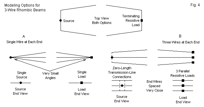
Fig. 4 shows two alternative methods of modeling the 3-wire rhombic. The top view would be the same for both models. It only indicates that we must use a blunt-end technique for the model. Given the discussion of blunt-end vs. pointed-end models in the previous section, we shall use a 1-segment end wire to form the blunt ends.
When we turn to end treatments in the lower portion of the figure, we can see more clearly our options. The simplest option (A) uses a single end wire at the source and load ends of the rhombic. The three side wires come together at each end of these wires. The source and the load are effectively centered within each end wire. The configuration presents two challenges to NEC as a calculating instrument. First, the three side wires approach the junction at very shallow angles, allowing for significant inter-penetration in the segments that form the junction. Second, NEC prefers a single segment on each side of a source segment prior to any division of the current.
The alternative to the single end wire is the use of separate end wires for each side wire (B). We may place these wires very close together so long as we allow spaces that are several times the wire radius. We may model the separate end wires using a spacing of 0.001 wavelength to achieve a simulation of a single wire. At the load end of the array, we may use separate terminating resistors on each line. The value for a 3-wire rhombic is simply 3 times the desired equivalent single terminating resistor, since the loads are in parallel. Since the loads do not have a physical dimension, they do not affect the wire spacing.
The source wires call for slightly different treatment, although we might use 3 sources and calculate their parallel value. A simpler procedure is to create a transmission line between each outer wire and the center wire. Since lines have no physical dimensions due to the wire geometry, we can assign them any desired length. Because we wish to simulate a parallel connection, we can assign a length of 1e-10 m or similar. The line's characteristic impedance can be virtually any value, since almost nothing happens over a near-zero line length. Using an impedance of about 600 Ohms will satisfy the situation. Of course, we place a single source on the center end wire, since transmission lines are in parallel with any source on the same segment.
One way to evaluate the alternative modeling techniques is to track what happens if we vary the value of the terminating resistor. As a test case, we can create 3-wire rhombics with 4 wavelength legs. Table 4 provides the comparison. Since the two types of models call for different optimized terminating resistors, the resistor ranges differ. As well, they differ from the ranges used in Table 3, which compared pointed-end and blunt-end models of 1-wire rhombics with 4 wavelength legs. The data in that earlier table will also be important to the evaluation of 3-wire models. The 3-wire models use 1-segment end wires, so the 1-segment blunt-end model of the single wire rhombic is the appropriate comparator. All models will be 1 wavelength above average ground and use 0.16" diameter lossless wire.
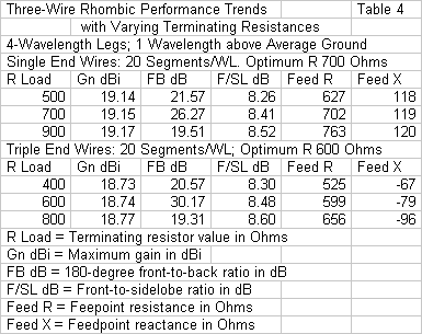
The use of a single end wire with 3 side wires joining at very small angles yields rather optimistic gain estimates compared to the 3-end-wire version of the model. In addition, the reactance undergoes virtually no change as we vary the value of the terminating resistor by 400 Ohms. Both of these data columns are at odds with the results for a 1-wire blunt-end rhombic model. In contrast, the 3-wire model that uses 3 end wires shows a more modest gain. As well, the pattern of capacitive reactance parallels the pattern shown in Table 3 for the blunt-end 1-wire rhombic. Finally, the triple end-wire model shows an optimized terminating resistor value of about 600 Ohms, a value that corresponds well with actual practice.
A second relevant test of the modeling options is to compare them by varying the spacing between side wires at the midline point. As a sample, I ran the models for both options at 3 spacing increments: 0.0125 wavelength (narrow), 0.025 wavelength (medium), and 0.05 wavelength (wide). Wide spacing is 4 times narrow spacing. The total distance at the midline between the top and bottom wires is twice the spacing increment. The end-wire spacing for the triple end-wire model does not change. The results of these tests appear in Table 5.
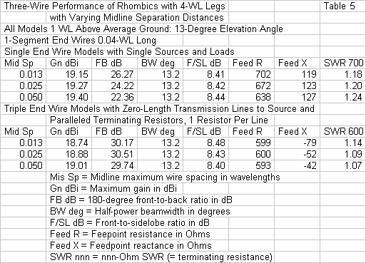
The weakness of the model using single end wires shows up in the table. The key datum is the feedpoint resistance, especially as we compare it with the corresponding datum for the triple end-wire model. As we increasing the wire spacing for the triple end-wire model, the reactance undergoes some change, but the resistance remains essentially constant. In contrast, the single end wire model shows only a small change of reactance, but a large change of resistance. As we increase the angle of the side wires as they approach their junction at the end wires, the resistive component moves closer to the 600-Ohm value of the triple end-wire model. The resistance change suggests that widening the angle at the junction reduces any calculation aberrations produced by wire inter-penetration.
Option B, the triple end-wire model provides results that are thus superior to those of option A in at least 2 ways. First, they are consistent with the results for the blunt-end 1-wire rhombic model. Second, the results are internally consistent relative to widening the midline spacing between wires. Although the reported gain is lower for the triple end-wire model, it nevertheless shows an increase with respect to increasing wire spacing. Moreover, it shows a useful gain over a 1-wire rhombic. For wide 3-wire rhombic midline spacing, the gain improvement can be up to about 1.6 dB, as shown in Fig. 5. The gain advantage is slightly less for narrower midline wire spacing.
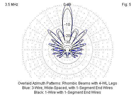
Note that the 3-wire rhombic not only magnifies the main forward lobe. As well, it enlarges virtually every other lobes in the radiation pattern proportionally, and without changing either the angle or the general shape of each lobe. Especially interesting in the pattern are the two innermost forward sidelobes. From the shapes, we can tell that they are in fact pairs of overlapping lobes. Both the 1-wire and the 3-wire models use an alpha angle of 24.5° to maximize gain. The lobe structure might change slightly with other values of alpha. For example, if we widen the angle further, the combined innermost sidelobes on each side of the present main lobe will eventually become stronger than the central lobe, resulting in a 3-lobe forward pattern.
To assure ourselves that we have fairly represented the advantages of the 3-wire rhombic over its 1-wire counterpart, we can perform one further test. We can increase the segmentation density of the triple end wire model and compare the progression with the one that we examined in the case of the blunt-end 1-wire rhombic. The comparison appears in Table 6. For both antennas, the steps use 20, 40, and 80 segments per wavelength, and the length of the end wire is reduced to maintain length parity with the adjacent segments of the side wires.
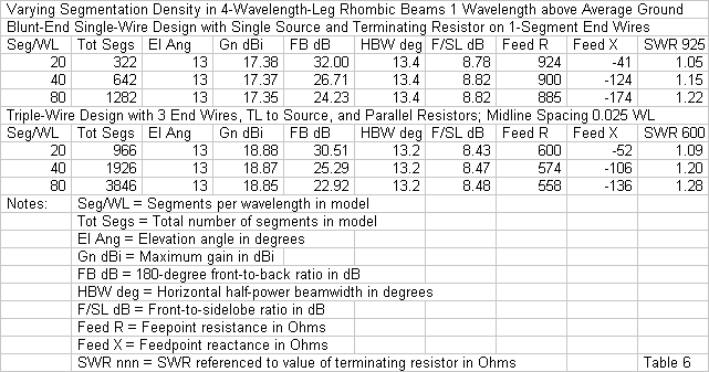
The 1-wire and 3-wire rhombics show quite precise parallels in the progression of values in each data column, indicating that the models are appropriate comparators. The only small divergence occurs in the reactance data, as the 1-wire rhombic model has a 133-Ohm total range, while the 3-wire model varies by only 84 Ohms. In both cases, the capacitive reactance increases as the end-wires become shorter. (However, even at the shortest length with the highest segmentation density, the modeled end wires are long compared to typical physical structures until we reach the high end of the upper HF range.)
The claims for 3-wire rhombics with which we began this section of notes find only partial confirmation in the models used to evaluate them. Using 3 wires does raise forward gain by an average of 1.5 dB for a 4 wavelength leg rhombic. The exact gain advantage depends on the wire spacing at the midline. As well, the optimum value for the terminating resistor drops from a value between 800 and 900 Ohms down to 600 Ohms. In both cases, the models reflect both calculations and practical experience with rhombics. However, reports of quieter operation--presumably meaning freedom from what Bruce called "static" in 1931--do not find confirmation in any property of the models. For a given leg length and value of alpha, the 3-wire rhombics produce patterns that are congruent in almost every detail with those produced by 1-wire rhombics. If 3-wire rhombics are in fact quieter than their 1-wire counterparts, the reasons must lie outside the realm of properties that NEC models can reveal.
Among the claims associated with 3-wire rhombics is a flatter SWR curve over an extended frequency range. Over the intervening decades since the appearance of the original literature on rhombic design, accounts have undergone truncation, especially after the heyday of rhombics had passed into the history of radio communications. My suspicion is that the claim of a flatter extended-frequency SWR applies only to the use of 600-Ohm transmission lines, likely occasioned by early difficulties in constructing mechanically stable wider lines with a higher characteristic impedance. If we match the line impedance to the terminating resistor, then extended-frequency SWR curves show no significant differences. For example, Fig. 6 provides SWR curves for the 1-wire blunt-end model and for the narrow-spaced 3-wire rhombic, with each using the terminating resistor as the SWR reference impedance.
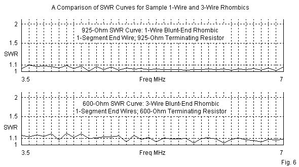
The curves use a 0.1-MHz increment, which is sufficient to pick up at least some of the peak values that might occur. However, the peak SWR is 1.2:1 or less for both antennas, suggesting that there is no significant difference between them. The slightly higher values in the 3-wire curve result from the fact that the similar reactive components in both antennas represent a higher percentage of the resistive component in the more complex array. In the end, reactance compensation during final design and construction, when combined with the selection of the correct feedline impedance, will do more for the flatness of the SWR curve than the presence of 3 wires.
(In fact, one account of single-wire rhombics suggested in one paragraph the use of 600-Ohm transmission line to the feedpoint and in another suggested that the terminating load might be placed conveniently near ground level by the use of another transmission line. If the termination line had a characteristic impedance of 800 Ohms, then line length would make no difference to performance, since it would match the presumed impedance of the terminating load and the antenna when viewed as a transmission line over ground. The account reflected common practice at the time of writing, and common practice is often the source of unnoticed inconsistencies.)
In the end, a 3-wire rhombic appears to have no calculable properties other than those associated with the simulation of a very large diameter wire through the use of multiple conductors. Cage antenna elements and multiple-conductor dipole and quad loop elements are fairly common practices to increase the effective diameter of an element without resorting to excessively heavy single large elements. The rhombic 3-conductor side wires function in much the same way, although their tapered arrangement makes the determination of a single effective diameter a somewhat uncertain calculation. The use of multiple side wires is optional unless one requires either the small gain advantage or the use of 600-Ohm lines and an equal value of terminating resistor.
Our small side-trip into 3-wire rhombics has had two goals. The first was to find an effective technique for modeling the antenna, a technique that would produce results that are fully consistent with both good NEC modeling practices and reports emerging from relevant 1-wire rhombic models. "Option B," the triple end-wire model accomplished this goal. The second goal was to understand within the limits of what models can tell us whether a 3-wire rhombic might have advantages over a 1-wire version of the same rhombic. Although we focused on a single mid-size rhombic (with 4 wavelength legs) designed to optimize gain, the results are suggestive for the entire range of possible rhombic sizes.
Conclusion
Our case study has illustrated one way in which an antenna with a relatively simple initial geometry can grow into a fairly complex model. The goal in all of the modeling exercises was to produce models that met as closely as possible all of the limits inherent in NEC (in this case, NEC-4). Key to the decisions as to which of alternative models best met these requirements were two factors. One was the internal consistency of results as tested by examining short progressions of variations in model designs and segmentation. The other factor was the reasonableness of the outcomes when compared to actual field practices in the construction of commercial rhombics.
One may well ask why we should be so finicky with the selection of a model geometry. At various places, I have noted that the models are suited only for developing general trends in rhombic performance and not for specific guidance in building a rhombic. Let's look at the trends in these brief notes and extrapolate them to a larger project, perhaps one involving a systematic exploration of rhombics of many leg sizes ranging from perhaps 2 to 11 wavelengths. The trends include not just the common concerns for forward gain and front-to-back ratio. They encompass as well trends in the value of the terminating impedance, the feedpoint resistance and reactance (at both the design frequency and over a usable passband), and the nature of the forward sidelobes. Geometrically, rhombic concerns do not cease with the selection of the leg length, but also include the angles of the wires and the effects of those angles on the resultant radiation pattern.
Fig. 5 overlaid patterns for single-wire and 3-wire rhombics in a direct comparison of radiation patterns. If we are to make such comparisons with any assurance that the comparison is valid, then the model on which each pattern is based must be consistent to the highest feasible level with the other model. Otherwise, we would have good reason to distrust the comparison--and the data that led up to it. One way to avoid rational distrust of model comparisons is to spend the required time to validate the models with respect to each other. These exercises have shown an example of the process.
In some cases, modelers appear to be content if they can achieve a model of the antenna they may be studying. In other cases--like this one--it is important to find the model for the geometry involved.