1. Free Space: the term "free space" indicates that absence of any surface beneath the antenna. Therefore, the antenna radiates in all directions without reflections (other than those that are a function of the modeled antenna structure itself). Choice of free space or "no-ground" is often the best for comparison of antennas of similar types. Moreover, it usually provides the most rapid calculation speeds and yields the highest accuracy output data.
The absence of ground may appear in a .NEC file as simply no ground entry, that is, no GN card. It may also appear as the following:
GN -1
2. Perfectly Conducting Ground: This option places beneath the antenna a perfectly conducting surface with perfect reflection properties--at a distance specified by the entries in the Z-axis column of the wire geometry cards. Although a wire may contact a perfect ground, horizontal wires should be above ground by a factor of at least the following:
where "h" is the wire height and "a" is the wire radius. In addition, h should be several times greater than "a" for valid results.
Since a perfect ground creates an image antenna identical to the original, it requires twice as long to fill the interaction matrix as a free space model. However, it is still faster than the use of either of the ground condition approximation systems. Thus, it has some interesting developmental applications. Selection of a perfect ground results in the following GN card entry:
GN 1
3. Finite Ground: Reflection Coefficient Approximation: Sometimes called the "fast" or "real" ground, this system employs an image model modified by Fresnel plane-wave reflection coefficient approximations for near fields. This system loses accuracy as an antenna is brought within several tenths of a wavelength toward the ground or lower and is most apt to relatively compact antenna structures. Nonetheless, it yields quite reasonable results, especially for preliminary developmental work, and is much faster than the more accurate Sommerfeld-Norton method.
Every finite ground requires at least the specification of values for the conductivity (in S/m) and the dielectric constant (permittivity) of the ground. A table of typical values for various types of soil appears further on in this colum. In general, vertical antennas close to the ground are more sensitive to changes in soil type than are horizontal antennas at their typical heights well above the ground surface. A typical GN card for a "fast" ground using "average" soil would appear as follows:
GN 0 0 0 0 13 .005
4. Finite Ground: Sommerfeld-Norton Method: The more accurate but slower (by a factor of 4) Sommerfeld-Norton (S-N, or SOMNEC) ground method uses exact solutions for fields in the presence of the specified ground and is accurate very close to ground. In fact, you may place wires as close to an S-N ground as to a perfect ground. For the highest accuracy of results for an antenna model above ground, the S-N method is the ground of choice. Except for the entry immediately following the card identification, a simple S-N ground entry looks identical to a reflection coefficient approximation ground entry card. For example,
GN 2 0 0 0 13 .005
As with all ground surfaces, the S-N ground extends indefinitely to the horizon. The S-N ground method also has provision for a second medium that extends a specified radius within ground specified in the card just shown. For our initial sampling of ground applications, we shall confine ourselves to simple grounds, that is to grounds whose properties extend from the antenna to infinity.
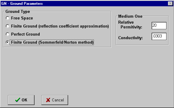
Selecting a ground type within NEC-2 takes different forms depending upon the way in which the program implements the process. The illustration above shows the pull-down box used in NEC-Win.
MININEC offers fewer ground type selections. Equivalent to the ones in NEC-2 are free space and perfect ground. The "real" ground system in MININEC is comparable (although not identical) to the "fast" ground system in NEC-2. It becomes less accurate for horizontal wires at heights greater than the accuracy limit for the NEC-2 "fast" ground system, and is generally considered inaccurate below 0.2 wavelengths of antenna height. (Note: these height limitations apply to horizontal or sloped wires with significant horizontally polarized radiation. Vertical antennas will require separate treatment.) In addition, the MININEC implementation of "real" ground applies only to far field calculations. MININEC calculates source impedance data using perfect ground, even when a "real" ground is selected. This feature can lead to source impedance errors for low horizontal wire antennas, such as those commonly used in the lower HF bands.
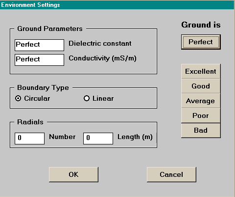
Selecting a MININEC ground type follows the same procedure as for NEC-2, with fewer selections. The illustration from NEC4WIN provides a sample.
EZNEC, which is an implementation of NEC-2, offers the use of the MININEC ground system in addition to the standard NEC-2 selections. This system is intended for use with certain types of models of vertical antennas, a topic we shall reserve for another column.
NEC and MININEC create from the two numbers a composite used in creating values to correctly derive the reflections that contribute to the far field. Be certain to correctly locate the entry position for each value in the set. Reversing the values can create some interesting but erroneous modeling results. I once encountered a Beverage antenna with an apparent gain of 17 dBi until the ground quality figures were correctly placed.
The following soil descriptions are commonly used in antenna modeling. Always substitute more precise values wherever known. The table represents an adaptation of values found in The ARRL Antenna Book (p. 3-6), which are themselves an adaptation of the table presented by Terman in Radio Engineer's Handbook (p. 709), taken from "Standards of Good Engineering Practice Concerning Standard Broadcast Stations," Federal Register (July 8, 1939), p. 2862. Terman's value for the conductivity of the worst soil listed is an order of magnitude lower than the value shown here.
Soil Description                   Conductivity   Permittivity   Relative
                                   in S/m         (Dielectric    Quality
                                                   Constant)

Fresh water                        0.001          80

Salt water                         5.0            81

Pastoral, low hills, rich
soil, typical from Dallas,
TX, to Lincoln, NE                 0.0303         20             Very Good

Pastoral, low hills, rich
soil, typical of OH and IL         0.01           14             Good

Flat country, marshy, densely
wooded, typical of LA near
the Mississippi River              0.0075         12

Pastoral, medium hills, and
forestation, typical of MD,
PA, NY (exclusive of mountains
and coastline)                     0.006          13

Pastoral, medium hills, and
forestation, heavy clay soils,
typical of central VA              0.005          13             Average

Rocky soil, steep hills,
typically mountainous              0.002          12-14          Poor

Sandy, dry, flat, coastal          0.002          10

Cities, industrial areas           0.001          5              Very Poor

Cities, heavy industrial areas,                                  Extremely
high buildings                     0.001          3               Poor
One of the preset values pairs offered by EZNEC is called "good" but uses the values for average soil from the table above.
First, modeled grounds consist of flat, uncluttered surfaces. Unless you specifically model ground clutter into the overall antenna model, its effects will not appear in the reported antenna performance figures and graphics.
Second, because modeled ground is flat from the antenna to the horizon (or stepped at a uniform radius or in a regular square), the modeling program does not take into account terrain variations that may be very important to a given antenna situation. Both K6STI and N6BV have developed experimental software to help translate modeled results into reasonable expectations for variable terrain.
Third, the ground beneath an antenna model is uniform to an indefinitely large depth. Although this model of ground is sufficient for the upper HF region and above, at the lower HF region and below, it may not accurately portray the ground conditions for an antenna. The ground beneath an antenna is normally stratified and changes quality with depth. Lower frequency signals can penetrate the earth to considerable depths and thus be variably affected by the changing soil quality. At best, for modeling purposes, one can develop only an average single pair of quality figures for complex soils.
In addition to these limitations, we have noted that some ground modeling systems have accuracy limitations for horizontal antennas. However, we might best view these from a modeled example.
In the tables, "N-Perfect" is NEC-2, perfect ground. "N-S-N" is the NEC Sommerfeld-Norton high accuracy ground system, generally considered to be the present standard of accuracy. "N-Fast" refers to the simplified ground system available in NEC. "N-MIN" points to a feature available only in EZNEC, which is the implementation of the MININEC ground system within NEC-2. "M-Perfect" in the gain table means perfect ground in MININEC, while "M-Real" refers to the real ground system in MININEC. In the source impedance table, "MININEC" covers both, since the source impedance is always calculated with reference to perfect ground in that system.
Gain and Elevation Angle of Maximum Radiation (Take-Off Angle) (xx/yy)

Height (wl/ft) N-Perfect N-S-N     N-Fast    N-Min     M-Perfect M-Real
1.0/34.5'      8.16/14*  7.59/14   7.58/14   7.58/14   8.17/14*  7.60/14
0.9/31.1'      7.58/16   7.16/16   7.16/16   6.94/16   7.59/16   6.94/16
0.8/27.6'      7.65/18*  7.09/17   7.10/17   6.93/17   7.66/18*  6.94/17
0.7/24.2'      8.46/21   7.44/20   7.47/20   7.65/20   8.48/21   7.67/20
0.6/20.7'      9.10/25   7.73/23   7.72/23   8.17/23   9.11/25   8.18/23
0.5/17.3'      8.36/30   7.25/28   7.20/28   7.26/28   8.35/30   7.25/28
0.4/13.8'      7.13/38   6.23/35   6.21/35   5.79/35   7.14/39   5.81/35
0.3/10.4'      6.91/54   5.70/49   5.66/49   5.21/49   6.92/56   5.22/49
0.2/ 6.9'      8.05/90   5.80/90   5.82/90   6.09/90   8.07/90   6.10/90
0.1/ 3.5'      8.66/90   3.55/90   4.21/90   7.45/90   8.67/90   7.48/90
*At the indicated heights, both NEC and MININEC register the second lobe above ground to be the take-off angle (49 degrees and 70 degrees, respectively for the two heights in order). However, there is no significant difference in strength between the two lobes over perfect ground, and the lower one is shown here for tabular consistency.
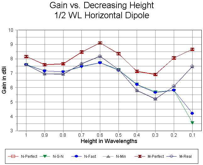
The maximum gain figures are charted in the figure above to save a bit of time in tracking the tables. (Detailed tracking is well advised to become familiar with the minor differences in expectations for reported figures.). The variations in gain with antenna height are in general quite natural. They can be tracked against changes in the elevation patterns for the antenna at each height. When we move from the most general level to specifics plotted in the graph, however, certain changes take on significance in terms of modeling accuracy.
The most significant portion of the graph is to the far right. Contrast the rise in reported gain from using the MININEC ground (either in MININEC itself or within the EZNEC version of NEC-2) with the gain decreases reported by the two NEC ground systems. Note also that the NEC "fast" ground reports a higher gain than the Sommerfeld-Norton system. Even though the MININEC ground reports parallel the reports over perfect ground, they are quite untrustworthy over real ground at these low heights.
There are a few less evident anomalies between ground systems. MININEC and NEC perfect ground lines are in excellent accord, as are the S-N and "fast" ground reports above 0.3 wl antenna height. However, NEC shows less variation in gain reports over the more reliable span of the graph than does the MININEC ground, whichever system uses it.
Source Impedance (R +/- jX Ohms)
Height (wl/ft)    N-Perfect  N-S-N      N-Fast     N-Min       MININEC
1.0/34.5'         71.0-10.0  71.1-6.0   71.3-6.0   71.0-10.0   70.7-9.8
0.9/31.1'         81.4-6.0   77.3-4.4   77.4-4.2   81.4-6.0    81.1-5.7
0.8/27.6'         81.1+6.8   78.0+2.9   77.8+3.2   81.1+6.8    80.9+6.9
0.7/24.2'         67.6+11.2  70.7+6.4   70.3+6.2   67.6+11.2   67.3+11.5
0.6/20.7'         57.6-2.0   63.9-0.3   64.0-0.9   57.6-2.0    57.3-1.5
0.5/17.3'         67.4-17.8  68.1-10.1  69.0-10.3  67.4-17.8   67.2-17.4
0.4/13.8'         89.8-14.0  81.6-8.8   81.9-9.0   89.8-14.0   89.2-13.9
0.3/10.4'         96.8+12.7  86.0+5.4   86.7+5.8   96.8+12.7   96.5+13.0
0.2/ 6.9'         68.6+36.8  72.1+17.8  71.9+20.1  68.6+36.8   68.8+37.1
0.1/ 3.5'         23.0+20.9  55.7+9.3   48.1+13.7  23.0+20.9   22.4+21.0
The gain inaccuracies at low heights reported by the NEC "fast" ground and the MININEC standard ground are accompanied by inaccuracies in reported source (feedpoint) impedance. Like the gain figures, MININEC figures are more extremely in error than those of the NEC "fast" ground, but both are untrustworthy.
Although I tend to distrust both the MININEC and NEC "fast" ground system below 0.25 wl horizontal antenna height, standard recommendation set a limit of about 0.2 wl. For reference, here is a chart of heights (in feet and meters) corresponding to 0.2 wl for selected frequencies in the amateur bands from 160 to 6 meters.
Frequency             0.2 wl            Frequency          0.2 wl
in MHz            Feet       Meters     in MHz         Feet       Meters
 1.875            104.9      32.0       18.1           10.9       3.31
 3.5               56.2      17.1       21.1            9.32      2.84
 4.0               49.2      15.0       24.9            7.90      2.41
 7.1               27.7       8.45      28.1            7.00      2.13
10.1               19.5       5.94      29.5            6.67      2.03
14.1               14.0       4.25      52.0            3.78      1.15
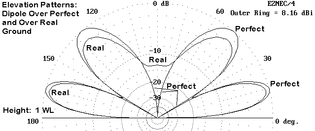
The first major difference with which to familiarize yourself is the patterns differences between using perfect ground and using any of the real grounds. The figure shows a sample for a dipole 1 wl up between modeling it over perfect ground and over real ground. The most striking feature, of course, is the higher gain over perfect ground. As well, note the depth of the nulls in the pattern over perfect ground and the shallower nulls over real ground. Straight up, the antenna over real ground has significant radiation, in contrast to the antenna over perfect ground. Note also that the two lobes over perfect ground are very close to equal strength, whereas over real ground, the second lobe is significantly reduced in strength.
A second set of differences appear if we model a horizontal antenna over various qualities of ground. Although some routinely assert that the ground quality makes virtually no difference for a horizontal antenna, this statement is only relatively true at antenna heights approaching and above 1 wl. At lower heights the ground can begin to make a notable numerical difference. Whether that numerical difference makes a significant operational difference requires to modeler to examine the antenna within its intended framework of use.
Suppose we place our 10-meter dipole at heights of 1 wl and 1/2 wl above ground. Then let us systematically change the ground quality through a few standard variations, as defined earlier in this column. Gain figures are in dBi, while the Take-off angle is in degrees.
Ground            1 wl Height                1/2 wl Height
Quality           Gain/TO Angle              Gain/TO Angle
Perfect           8.16/14                    8.34/30
Very Good         7.83/14                    7.67/28
Average           7.58/14                    7.18/28
Poor              7.56/14                    7.13/28
Very Poor         7.16/14                    6.43/27
VG to VP gain
  difference      0.67 dB                    1.24 dB
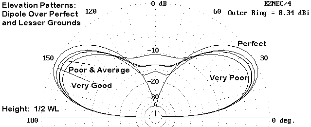
Increasing the antenna height by double almost halves the gain differential between very good and very poor soils. At low heights, as shown in the elevation patterns in the figure, typical of horizontal antennas for the lower HF bands, soil quality can make a difference in the potential performance of a horizontal antenna. Above 1 wl for the antenna height, the difference becomes ever less significant.
However, there is another entire class of antennas with which we must contend: the vertically polarized antennas. We should not expect from this unruly antenna group the well-behaved figures we obtained for horizontally polarized antennas. Making sense of modeling verticals at, near, and well above ground will be our task next month.