In Parts 1 and 2, we examined the simplest unterminated and terminated long-wire arrays using a single end-fed wire in both cases. Unterminated wires yield essentially bi-directional patterns in line with the wire--more in line as the wire grows longer as measured in wavelengths. There is a small residual front-to-back ratio associated with long-wire end-fed wires, with the stronger lobes toward the open or un-fed end of the wire. Adding a terminating resistor converts the bi-directional wire into a directional beam, although the gain is about 4 dB lower than the strongest lobes of the unterminated wire of the same length. At the end of Part 2, we summarized the shortcomings of the single-wire terminated end-fed wire beam: "The lobes are split. There are many side lobes. The forward gain is low." To overcome some of these problems, early antenna experimenters invented the unterminated V array and the terminated V beam. We shall look at each of these antennas in order, since we have some questions that parallel those connected with the single wire terminated and unterminated antennas. For example, will the terminated V beam show the same gain deficit relative to the unterminated V array as the terminated single-wire did relative to its unterminated version? The V antennas are so intimately related to the single long-wire antennas that before we move onward to rhombics, we shall do a more detailed comparison.
V-Array Basics
The V array derives directly from the single long-wire antenna. In fact, a V array is nothing more than two single long-wires connected at a feedpoint junction and fed in series. The V array makes use of one of the problems for a single wire: the two main lobes do not come completely together to form a single lobe. The V array turns the problem into an advantage. If we angle each leg of the V in just the right way, we can get two of the lobes--one from each leg--to point in the same direction and let their gain levels add. Fig. 1 shows the outline of how we obtain a true bi-directional unterminated array from 2 long-wire antennas.
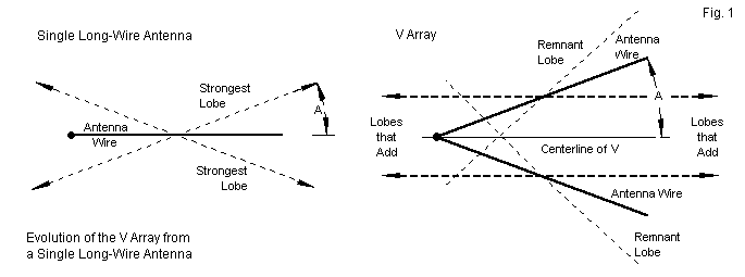
On the left is a representation of a single long-wire antenna (bold solid line) and the headings of its main or strongest lobes (dotted line). Note that we use the wire center as a conventional origin of the lobe indicators. Since the dotted lines represent a far field pattern, the antenna (in relation to the pattern) would have an infinitesimal size. When thinking about the pattern, mentally shrink the antenna until it almost disappears.
In Parts 1 and 2, we represented the angle taken by the individual lobes as an angle relative to the tangent to the wire, that is, relative to a broadside direction. In this episode, we are interested in angle A (usally shown as an alpha in texts). The old angular value and A add up to 90 degrees, so conversion is easy.
If we now use 2 wires to form a V, we can set each one at angle A relative to the centerline of the V. So the total angle between wires is 2A. By aligning the wires in this way, a main lobe from each wire at each end will fall into alignment and add up to a new higher gain level. As well, there will be only 1 main lobe in each direction in line with the wire. The remnant lobes become sidelobes of the array. Note that this strategy is in principle similar to the strategy of bending a long single wire in the middle to obtain lobes that add rather than going in different directions. Indeed, the required angle for each type of design is almost the same: angle A. Indeed, for the same quantity of horizontal wire, a directional V beam and a terminated bent single wire have about the same gain. The difference is largely one of halving the total overall length (and the acreage required beneath the antenna) for a doubling of the smaller required width.
We are fortunate, since we can refer to Part 1 and find the heading of the main azimuth lobes for each test length of long wire antenna. The following table lists those headings as well as the resultant value of angle A. The table also shows several other values. The next column lists a calculated value for angle A that we shall explain following the table. The final columns show the angles associated with corresponding long-wire terminated beams. These values will not play a role in our work. They only illustrate the fact that forming a terminated beam from the long-wire antenna does compress the angle between the maximum gain points on the beam forward pattern, in part due to the presence of the vertical wires necessary to complete a practical installation.
Long-Wire Azimuth angles of Maximum Radiation and Corresponding A-Angles
                   Unterminated Long-Wire                    Terminated Long-Wire
Antenna     Azimuth Angle  Angle A   Calculated Angle      Azimuth Angle   Angle A
Length WL   degrees        degrees   A degrees             degrees         degrees
 2          56             34        35.4                  -----           -----
 3          63             27        27.6                  66              24
 4          67             23        23.0                  70              20
 5          70             20        19.8                  72              18
 6          72             18        17.6                  74              16
 7          74             16        15.8                  75              15
 8          76             14        14.4                  77              13
 9          77             13        13.2                  78              12
10          77             13        12.2                  78              12
11          78             12        11.3                  79              11
If we did not have access to NEC-calculated values for the azimuth angles for the strongest long-wire lobes, we could have resorted to an approximation equation for calculating the value of angle A.
Angle A = arccos [(N-0.5) / N] - 6
Angle A is in degrees, while N is the length of the long-wire legs in wavelengths. I adapted and adjusted this equation from one found in Balanis' account of long-wire antennas. Within the confines of the lengths used for our test NEC-model cases, the equation is quite adequate for forming models of V arrays. More complex angle calculation devices exist, but they turn out to be almost spuriously precise. The gain of a V array changes very little using angle-A values that are plus or minus a full degree from the listed values. The tolerances become considerably tighter, however, if we increase the leg length well beyond the limits of the table. Hence, NEC models may be the best way to indirectly obtain the requisite values for angle A. (For much longer antennas, it may be useful to increase the resolution of the azimuth patterns from which we indirectly derive angle A. NEC is fully capable of handling 0.1-degree increments between pattern samples. In such cases, the headings for the strongest lobe will also resolve to a tenth of a degree.)
Note: The models in this part of our work make use of angle A as derived from our modeling of single long-wire antennas. They do not necessarily optimize that angle for maximum gain. There is a slight difference.
For basic model testing, I chose the 10 wavelength V array using 13 degrees as the value of angle A. Relative to the array centerline, shown in Fig. 1, the array is 9.75 wavelengths long and 4.5 wavelengths wide at the open end. Like the antennas in Parts 1 and 2, this one also uses perfect or lossless wire at 20 segments per wavelength. The main tests will place the antenna 1 wavelength above average ground (conductivity 0.005 S/m, permittivity 13). However, for initial tests on the 10 wavelength model, I placed it over very good, average, and very poor soil in order to see what differences ground quality might make to performance. The following table emerged from those tests.
10-Wavelength Unterminated V Array 1-Wavelength Above the Indicated Soil Type
Angle A = 13 degrees; Elevation angle = 10 degrees
Soil Type    Gain    Front-Back     Beamwidth
             dBi     Ratio dB       degrees
Very Good    17.21    2.55           11.0
Average      17.24    2.47           10.2
Very Poor    17.17    2.37            9.8
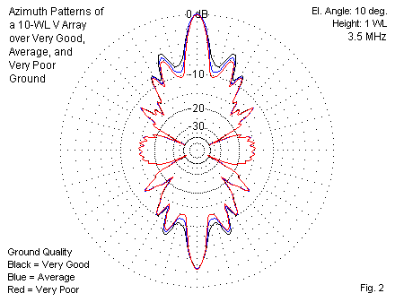
Unlike other antennas that we have surveyed in this collection of notes, the V array showed almost no change in its pattern, despite the wide range of soil qualities. The conductivity of the soils ran from 0.0303 S/m for very good ground down to 0.001 S/m for very poor ground. The relative permittivity range from very good to very poor was 20 down to 5. Fig. 2 overlays the azimuth patterns for the 3 models. Except for a few distinguishable differences in nulls, the patterns almost perfectly coincide with each other. In the realm of bi-directional unterminated long-wire antennas, the V array may prove to be a good selection for use over relatively poor soils.
In the initial tests, I also tried the 10 wavelength V array using copper wire over average ground to obtain a sense of what wire losses might be. As in past models, the wire diameter is 0.16" (AWG #6) to allow scaling of the 3.5 MHz test models to other frequencies in the amateur HF range.
10-Wavelength Unterminated V Array 1-Wavelength Above Average Soil
Angle A = 13 degrees; Elevation angle = 10 degrees
Wire Type    Gain    Front-Back     Beamwidth
             dBi     Ratio dB       degrees
Lossless     17.24    2.47           10.2
Copper       16.73    2.68           10.2
As the simple comparison shows, we lose about 0.5-dB relative to maximum gain by using copper wire. I would view such losses as insignificant, especially since we have no way to recover them without a 20 wavelength supply of super-conducting wire.
In order to compare the performance of a single unterminated wire to that of a V array, I constructed models of the V array using legs that ran from 2 to 11 wavelengths. The following table lists the value of angle A, the elevation angle for maximum gain, the maximum gain value, the remnant front-to-back ratio, and the beamwidth of the strongest main lobe. In addition, for easy reference, the table also lists the maximum gain of the corresponding single unterminated long-wire antenna and the gain differential between it and the V array.
Performance of V Arrays 1-Wavelength Above Average Ground                 Single Long-Wire
Leg Length   Angle A   Elevation  Max. Gain   Front-Back   Beamwidth      Max. Gain       Difference
WL           degrees   Angle deg  dBi         Ratio dB     degrees        dBi             dB
 2           34        13         13.60       1.37         20.2           10.27           3.33
 3           26        13         14.65       1.84         17.2           11.32           3.33
 4           23        12         15.48       1.88         14.4           11.99           3.49
 5           20        12         15.97       2.05         13.2           12.48           3.49
 6           18        12         16.25       2.27         12.2           12.90           3.35
 7           16        11         16.56       2.36         11.8           13.24           3.32
 8           14        11         16.75       2.44         11.8           13.50           3.25
 9           13        11         16.99       2.44         11.4           13.72           3.27
10           13        10         17.24       2.47         10.2           13.96           3.28
11           12        10         17.35       2.56         10.2           14.15           3.20
The tabulated data shows the usual progression of increasing gain and decreasing beamwidth as we lengthen the legs of the antenna. As well, length-for-length, the V array shows a maximum gain that is somewhat over 3-dB greater than the gain of a single long-wire antenna having the same length. (One might well dispute the length equivalence, arguing that the centerline of the V array is always shorter than the centerline of the corresponding single long-wire antenna. However, with 10 wavelength legs, the centerline difference is only about 1/4 wavelength due to the gradual narrowing of the angle (2A) between the wires.)
Perhaps the most intriguing set of numbers falls in the beamwidth column. For leg lengths beyond about 3 wavelengths, the antenna requires careful alignment for the main lobe (or lobes) to hit a communications target. In fact, V arrays (and beams) found their main use as antennas having communications targets falling within a small radius. One technique used to steer the antenna's main lobe was to set multiple Vs in a physically serial arrangement that did not necessarily form a straight line Thus, one antenna could bend the beam of the first. We should also remember that high quality copper wire in the late 1920s and through the 1930s was not as cheap as it is today, when measured against other prices. Many amateurs used less expensive phosphor-bronze wire for antennas, and government and commercial wire antenna installations were major investments. Although we today may doubt the precision that one might achieve by attaching wire to wooden telephone and telegraph poles, the engineering calculations were as precise a available techniques permitted. (Laport's Radio Antenna Engineering from 1952 has an interesting gallery of photos of mainly RCA antenna installation going back as far as the 1930s. Wooden poles--some spliced to increase their height--outnumber metal masts and towers. We may also find it interesting that many installers working with hand tools wore neckties and fedora hats on the job.)
The V array is not an antenna for broad coverage of the horizon. Its wire foundation makes it immovable, and the gain comes at the expense of beamwidth. Hence, its best use is as a point-to-point antenna, where the reliability of a single communications link is more important than communications with many diverse places on the horizon. The gallery of sample elevation and azimuth patterns in Fig. 3 will reinforce this judgment.
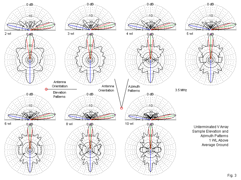
Compared to the single long-wire antenna, the V array shows significantly smaller elevation lobes above the main lobes. The azimuth sidelobes, while still pronounced in the off-heading forward areas, are generally smaller than those of a single unterminated wire antenna. Many of the sidelobes from each leg tend to counter corresponding sidelobes from other legs, in part due to having different headings and in part due to the spacing between the legs. The azimuth pattern for the 4 wavelength model shows perhaps the tightest wasp-waisted pattern. In contrast, the elevation upper lobes tend to decrease in strength in more direct proportion to the length of the legs. However, due to the interaction of the lobes from each leg and the changing included angle from one model to the next, we cannot characterize the patterns by reference to the number of lobes, as we did with the single long-wire end-fed antenna.
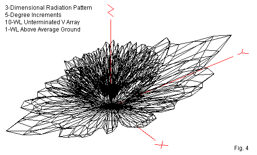
The 3-dimensional radiation pattern shown in Fig. 4 has a peculiarly crystalline appearance, given the 5-degree increment between sampling points. Nevertheless, the main lobe extremities show well. Still, one might best refer to the 2-dimensional plots before attempting to characterize the upper-angle lobes. Although there are still many lobes--as there will be for virtually any long-wire antenna--their strength relative to the main lobes is considerably weaker than is the case for a single wire.
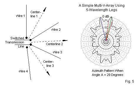
There is no rule that we must always optimize a V array for maximum gain. At certain values for angle A, the beamwidth will widen. Of course, the new value for A varies with the length of the legs. As well, a widening of a few degrees will actually narrow the beamwidth. However, by judicious modeling or experimentation, one can find a usable beamwidth before the pattern degenerates into peaks with a very deep null between them. For example, with 5 wavelength legs, the peak-gain angle is 20 degrees (or 40 degrees between wires). The beamwidth is 13.2 degrees. By widening angle A to 29 degrees (58 degrees between wires), the effective beamwidth becomes about 35 degrees. With a pre-planned selection of centerline headings, it is possible to cover much of the horizon in a switched set of V arrays in which each interior leg serves 2 arrays. Fig. 5 shows the general scheme and a sample azimuth pattern. For some installations, similar schemes can be tailored to the operating site and communication needs. The 13.4-dBi gain of each V-pair still out-performs individual 5 wavelength wires.
The potentials for V arrays are larger than suggested by this introduction to them. However, it is time to terminate this initial discussion and the V array itself.
V-Beam Basics
The terminated V array forms a V-beam, that is, a directional terminated V array. The technique seems simple enough. We simply place a non-inductive terminating resistor at the end of each leg. However, the resistor cannot simply float at the terminating end of the wire. One option is to bring the terminated end of the leg wire to ground. Alternatively, we may run a wire between the two terminated wires end and place the non-inductive resistor at the center.

Fig. 6 shows 4 classic implementations of the terminated V-beam. Model A places the feedpoint close to ground and slopes the legs upward to their normal (1 wavelength) height. (The opposite slope for the array is also possible. See model A1.) The terminated ends run vertically to the ground, with the terminating resistors at ground level. The model will use the same ground-rod technique used in constructing models of single terminated long-wire directional antennas. However, none of the models will use a vertical wire at the feedpoint end. The single long-wire beams could use the vertical feedpoint end with the actual feedpoint close to ground. If we apply that same technique to the V-beam, we end up with the 2 legs in parallel, which does not yield much gain or directivity. The source-ends of the legs must have the feedline across them in a series connection to yield the correct addition of peak lobes from each leg.
Selecting the correct values of the 2 terminating resistors is not so simple as it was with the single long-wire beam. As the following trial table shows, the value is not exceptionally critical, although we may have reasons for choosing one value over another. For design purposes, the reasons may involve the best compromise among gain, front-to-back ratio, and impedance. In practical installations, the reasons generally focus on what non-inductive resistors may be available. The test table (and others to follow) uses NEC-4 models with 5 wavelength legs 1-wavelegnth above an average SN ground.
Test Performance Values for Modeling Option A

Terminating     Maximum      Front-to-Back     Beamwidth     Elevation     Feedpoint Z     1000-Ohm
Load Ohms       Gain dBi     Ratio dB          degrees       Angle deg     R+/-jX Ohms     SWR

600 x2           8.89        23.15             12.2          15             988 + j184      1.20
700 x2           8.91        22.40             12.4          15            1043 + j145      1.16
800 x2           8.93        20.58             12.4          15            1091 + j109      1.14
The sloping version of the terminated V-beam shows a serious gain deficit relative to level models (options B, C, and D in Fig. 6). Gain is 4- to 5-dB lower than for the other versions. Therefore, we should test further V-beam designs. NEC calculates that each terminating resistor dissipates about 21% of the applied power, using the 700-Ohm resistor in each leg.
If we slope the V-beam in the other direction, with the feedpoint high and the terminations low, we do not see much change in the performance, except for a reduction in the front-to-back ratio and a reduction in the terminating resistor. Let's call the reverse slope model A1.
Test Performance Values for Modeling Option A1

Terminating     Maximum      Front-to-Back     Beamwidth     Elevation     Feedpoint Z     1000-Ohm
Load Ohms       Gain dBi     Ratio dB          degrees       Angle deg     R+/-jX Ohms     SWR

400 x2           8.60        18.90             21.0          14            1032 + j107      1.12
500 x2           8.60        18.06             21.2          14            1096 - j  6      1.10
600 x2           8.63        15.99             21.2          14            1141 - j109      1.18
The theory behind the reverse slope is an attempt to lower the elevation angle of maximum radiation. However, the result is an antenna that is on average much lower than a model that is level at 1 wavelength. Hence, the net elevation angle, while 1 degree lower than for version A is still higher by 2 degrees than the other models (B, C, and D) in this sequence. The model A gain deficit still remains, with a gain level that is barely 1 dB higher than a 1/2 wavelength dipole at 1 wavelength above average ground.
Model B uses the same layout as Model A, but raises the feedpoint to the same height as the remainder of the antenna. Like Model A, B uses a pair of terminating resistors. The gain and elevation angle of maximum gain return to normal values, as shown in the following test table.
Test Performance Values for Modeling Option B

Terminating     Maximum      Front-to-Back     Beamwidth     Elevation     Feedpoint Z     800-Ohm
Load Ohms       Gain dBi     Ratio dB          degrees       Angle deg     R+/-jX Ohms     SWR

600 x2          13.00        20.62             13.8          12             830 + j133      1.18
800 x2          13.02        18.41             13.8          12             926 + j190      1.30
1000 x2         13.07        16.00             13.8          12            1002 + j242      1.42
The gain level of this model changes very slowly with changes in the values of the terminating resistors. Hence, the table proceeds in 200-Ohm increments. Selecting the most optimal combination requires some decision-making based on criteria. In the absence of practical operating goals, I chose the 600-Ohm resistors, since they yielded the highest front-to-back ratio in the group, along with having the lowest order of feedpoint reactance. The 600-Ohm resistors dissipate about 22% of the applied power--each.
Model C uses the same feedpoint treatment as model B. However, instead of bringing 2 vertical wires to ground, with 2 attached resistors, model C uses a straight connecting wire between the far ends of each leg. For the 5 wavelength legs of the test model, the crossing wire is about 3.4 wavelengths. At the center of the wire, we place a single non-inductive resistor. As the following table will show, the connecting wire is not inert, but an active part of the overall antenna.
Test Performance Values for Modeling Option C

Terminating     Maximum      Front-to-Back     Beamwidth     Elevation     Feedpoint Z     900-Ohm
Load Ohms       Gain dBi     Ratio dB          degrees       Angle deg     R+/-jX Ohms     SWR

800             14.38        12.73             12.6          12             981 + j192      1.25
900             14.35        13.76             12.6          12             949 + j147      1.18
1000            14.34        14.73             12.6          12             919 + j110      1.13
The crossing horizontal wire between the V-leg ends contributes to the array gain in both directions. Hence, the peak forward gain is slightly higher than for model B, but the front-to-back ratio is much lower. If we select the 900-Ohm terminating resistor, NEC calculates that it will dissipate about 46% of the applied power.
Model D also uses a crossing wire with a single terminating resistor at its center. However, it brings the crossing wire much closer to ground level. In the model, the wire is 0.001 wavelength above ground, just enough for the wire to clear the ground by several wire diameters. Each end of the V assembly runs a vertical wire down to the junction with the low crossing wire. As the table shows, this arrangement produces one of the most stable configurations relative to changes of gain with changes of the terminating resistor value.
Test Performance Values for Modeling Option D

Terminating     Maximum      Front-to-Back     Beamwidth     Elevation     Feedpoint Z     750-Ohm
Load Ohms       Gain dBi     Ratio dB          degrees       Angle deg     R+/-jX Ohms     SWR

600             13.02        21.26             13.4          12             761 - j 49      1.07
800             13.03        20.64             13.4          12             754 - j 55      1.08
1000            13.03        20.19             13.4          12             749 - j 59      1.08
1200            13.03        19.85             13.4          12             744 - j 63      1.09
Not only is the gain stable across a 2:1 range of resistor values, but as well both the front-to-back ratio and the feedpoint impedance are equally stable. NEC calculates that in its altered position, the 1000-Ohm terminating resistor dissipates only 2.8% of the applied power, although this result stems from the proximity of the crossing wire to ground in the model. The actual dissipation may be much larger for only small increases in resistor and wire height. Nevertheless, using a very low crossing wire removes it from having a significant affect on the radiation pattern. In fact, the data for models B and D are quite similar, although model D appears to be the more stable. Further test of the V-beam using various leg lengths will employ this model and its 1000-Ohm resistor.

Fig. 7 provides azimuth patterns for each of the 5 wavelength V-beam models. They show a family resemblance, especially in the forward structure of the lobes. The sidelobes of model A appear stronger because the forward gain is 4-dB or more weaker than for the other models. The data had suggested a close correlation between model B and model D, and the azimuth patterns tend to confirm the suggestion.
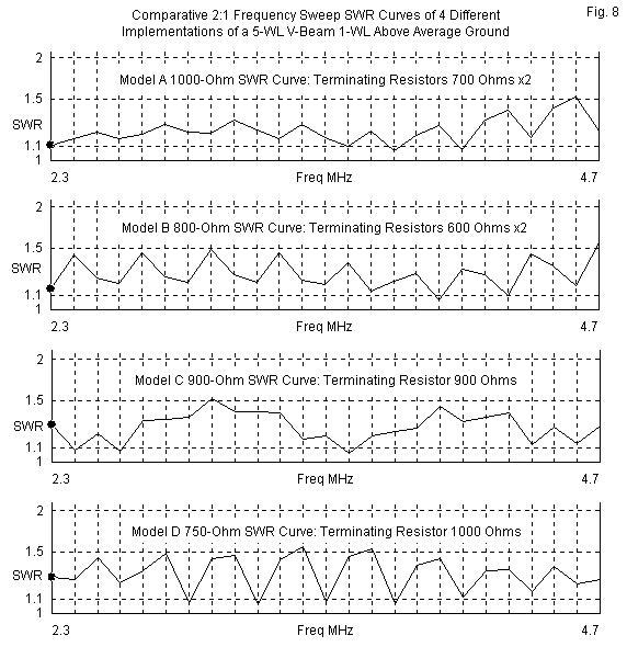
Although the 4 models of a V-beam use different arrangements and terminating resistor values to arrive at their patterns, all of them have the wide-band characteristic that we saw in the case of single long-wire beams. Fig. 8 provides the SWR curves over a 2:1 frequency range using the optimal feedpoint impedance relative to the indicated values of terminating resistor or resistors. In each case, for the range tested and beyond, a single impedance-transformation device would suffice to match the antenna to most equipment. What all the SWR patterns share in common is the existence of ripples of non-harmful but noticeable proportions. These ripples are indications that the selected terminating resistor value(s) did not result in the closest equality between the terminating resistor and the feedpoint impedance. Instead, the final component selection rested on other criteria, such as the resulting pattern, etc.
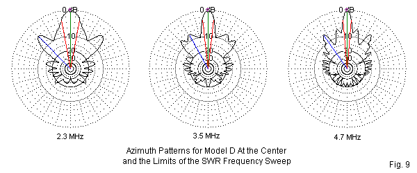
The broad SWR bandwidth of the single long-wire directional antenna is completely reliable, since the general pattern of the antenna is predictable in terms of gain and beamwidth. However, the V-beam has a more limited usable bandwidth due to restrictions created by the angle between the wires (2A). At some frequency above and at another below the design frequency, the value of angle A will no longer be suitable to support a single forward lobe. As shown in Fig. 9, a 2:1 operational range is feasible for the 5 wavelength V-beam that is 1 wavelength above ground at the center frequency.
Performance of a 5-Wavelength 3.5-MHz V-beam 1 Wavelength Above Average Ground
Model D: Terminating Resistor: 1000 Ohms
Frequency       Maximum      Front-to-Back     Beamwidth     Elevation
Mhz             Gain dBi     Ratio dB          degrees       Angle deg

2.3              9.84        33.30             21.8          17
3.5             13.03        20.19             13.4          12
4.7             14.42        23.77              9.8           9
When evaluating both the patterns and the tabular data, remember that at the low end of the sweep, the antenna is only 0.66 wavelength above ground, accounting for the higher elevation angle. Similarly, at the top of the sweep, the antenna is 1.34 wavelengths above ground. The changing height is an additional variable relative to the departure from an optimal value for angle A, and both contribute to the listed performance values.
Parallel to our investigation of the unterminated V array, I ran model D with a 1000-Ohm terminating resistor over several ground types. As shown in the table below, the gain changes by under 0.5 dB across the range of soils. The other values are equally stable, presenting no difficulties to using the V-beam over virtually any ground environment.
5-Wavelength Terminated V Array 1-Wavelength Above the Indicated Soil Type
Angle A = 20 degrees; Elevation Angle = 12 degrees
Soil Type    Gain    Front-Back     Beamwidth    Feedpoint Z     750-Ohm
             dBi     Ratio dB       degrees      R +/- jX Ohms   SWR
Very Good    13.18   18.89           14.4        753 - j 97      1.14
Average      13.03   20.19           13.4        749 - j 59      1.08
Very Poor    12.72   24.15           13.0        782 - j 27      1.06
Likewise, the use of a real material, such as copper wire, in place of the modeled perfect wires, offers no hindrance to the V-beam. As the following table shows, the loss due to the use of copper wire for the 5 wavelength V-beam is about 0.1-dB over average ground. All of the other performance values are completely stable.
5-Wavelength Unterminated V Array 1-Wavelength Above Average soil
Angle A = 20 degrees; Elevation Angle = 12 degrees
Wire Type    Gain    Front-Back     Beamwidth    Feedpoint Z     750-Ohm
             dBi     Ratio dB       degrees      R +/- jX Ohms   SWR
Lossless     13.03   20.19           13.4        749 - j 59      1.08
Copper       12.93   20.43           13.4        752 - j 52      1.07
The full table of performance values below rests on model D, the version with a single terminating resistor centered on a wire between the V-leg end, but very close to ground level. The table does not include power dissipation values, since they likely depend on the very close proximity of the modeled resistance to the ground, as well as energy lost to ground due to the proximity. Hence, the exact dissipation values will vary with the actual height of the cross connecting wire. The table does include values for angle A, the elevation angle of maximum gain, the modeled maximum gain, the 180-degree front-to-back value, the beamwidth, the feedpoint impedance, and the 750-Ohm SWR. In addition, the table shows the maximum gain of the corresponding unterminated V array and the gain difference relative to the V-beam.
Note: Once again, the value of angle A is derived from our long-wire antennas and is not adjusted to achieve maximum gain.
Performance of V Beams 1-Wavelength Above Average Ground                                           Unterminated V Array
Leg Length   Angle A   Elevation  Max. Gain   Front-Back   Beamwidth   Feedpoint Z    750-Ohm      Max. Gain   Difference
WL           degrees   Angle deg  dBi         Ratio dB     degrees     R +/- jX Ohms  SWR          dBi         dB
 2           34        13          9.88       36.86        21.0        772 + j16      1.04         13.60       3.72
 3           26        13         11.41       21.70        17.4        750 - j66      1.09         14.65       3.24
 4           23        12         12.35       22.90        14.8        772 - j38      1.06         15.48       3.13
 5           20        12         13.03       20.19        13.4        749 - j59      1.08         15.97       2.94
 6           18        11         13.50       19.97        12.4        741 - j39      1.06         16.25       2.75
 7           16        11         13.86       20.17        12.0        742 - j40      1.06         16.56       2.70
 8           14        11         14.07       19.89        12.0        731 - j42      1.06         16.75       2.68
 9           13        11         14.29       19.54        11.4        724 - j51      1.08         16.99       2.70
10           13        10         14.59       19.32        10.4        721 - j42      1.07         17.24       2.65
11           12        10         14.74       19.40        10.2        716 - j43      1.08         17.35       2.61
The table shows a very normal increase in gain with leg length at the optimal angle A. Both the elevation angle and the beamwidth for the V-beam tightly correspond to comparable values for the unterminated V array, with no decrease in beamwidth as we experienced with the transition from unterminated long-wire to terminated long-wire antennas. The 180-degree front-to-back ratio holds around the 20-dB mark, and the impedance is exceptionally stable throughout the span of leg lengths. (The stability of the impedance values is an especially good marker of the adequacy of using values for angle A derived from the unterminated single long-wire models.) As a side note, compare the V-beam entry for 4 wavelength legs to the data for the bent terminated long-wire in Part 2. The gain values a virtually identical, although the V-beam improves the front-to-back ratio and reduces many of the sidelobes. Both antenna require 8 wavelengths of horizontal wire.
The V-beam, like the terminated long-wire antenna, shows a decrease in maximum forward gain relative to the unterminated version of the antenna. However, the V-beam decrease is about a dB less than for the single long-wire beam. Nevertheless, the reason for using a V-beam instead of an unterminated V array is the directivity of the pattern, with the loss of gain accepted as a fair penalty for the reduced sensitivity to the rear. If rearward pattern reduction is not a priority for a given installation, then the unterminated V array may be the better choice of antennas. Fig. 10 provides a gallery of selected elevation and azimuth plots that show the evolution of radiation patterns with increasing leg length in the V-beam. You may wish to compare these plots directly to corresponding plots in Fig. 3 for the unterminated V array.
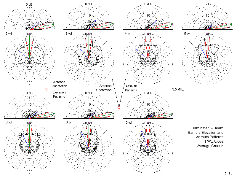
The azimuth patterns have two major characteristics that we should note. First is the narrowing of the beamwidth as we make the antenna longer, a feature that also attaches to the V array. Second is the development of the secondary lobes in the 2 forward quadrants. These lobes are a function of the narrowing angle between wires and the lobes on each wire that do not add to form the strongest center lobe.
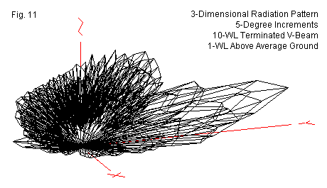
The most notable elevation-plot feature is the relative absence of strong secondary elevation lobes. Only the lobes closest to the main elevation lobe exceed the -20-dB level in strength relative to the main lobe. We may better gauge the upper-level lobe structure from a 3-dimensional radiation pattern, such as the one in Fig. 11. The 10 wavelength V-beam used to generate the plot clearly shows the lowest level. The apparent second level is actually a part of the main lobe. The stepped appearance is due to the 5-degree increments in pattern sampling. The next strongest level to the main lobe occurs near the 40-45-degree region and is 15-20-dB weaker than the main lobe. Although there are still many upper-level lobes in the pattern, their strength is operationally insignificant.
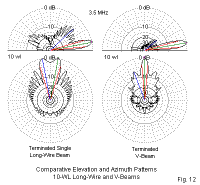
Perhaps an appropriate way to conclude our exploration of the V-beam is by comparing it, length for length, with the corresponding single long-wire terminated beam. Fig. 12 provides a pattern comparison, using 10 wavelength versions of both antennas. The elevation patterns shows the V-beam's reduction in relatively useless upper level lobes. The azimuth pattern shows the V-beam's tighter control of sidelobes, especially in the forward quadrants. However, for some communications tasks, the terminated long-wire may have the more useful beamwidth, despite the null between forward peaks.
The following table summarizes the gain and beamwidth differentials between the 2 terminated long-wire directional antennas.
Long-Wire and V-beam Gain and Beamwidth Values for 3- to 11-Wavelength Arrays
              Terminated Long-Wire        Terminated V-Beam
Length        Gain      Beamwidth         Gain      Beamwidth        Gain Difference
WL            dBi       degrees           dBi       degrees          dB
 3             7.11     69                11.41     17               4.30
 4             7.99     59                12.35     15               4.36
 5             8.65     51                13.03     13               4.38
 6             9.15     46                13.50     12               4.35
 7             9.57     44                13.86     12               4.29
 8             9.92     40                14.07     12               4.15
 9            10.20     37                14.29     11               4.09
10            10.47     36                14.59     10               4.12
11            10.70     33                14.74     10               4.04
The V-beam shows a consistent 4-dB+ gain advantage over the terminated long-wire antenna, but its beamwidth is consistently 1/3 to 1/5 the values for the long-wire. The terminated long-wire directional antenna, of course, shows a null between peaks, and for lengths from 3 to 6 wavelengths, the null is deep enough (>3dB) for modeling software to recognize two distinct forward lobes. The table does not itself make a judgment, but simply facilitates a comparison of the results in Part 2 of this series and the results obtained for this part.
Conclusion to Part 3
On this leg of our journey through the classical long-wire antennas, we have focused on the V antenna in both unterminated and terminated forms. By properly angling the legs of the V, the antenna combines a major lobe from each wire to form a single lobe in the forward direction. Of course, the unterminated V array has a similar lobe to the rear and it is is only slightly weaker than the lobe pointing away from the feedpoint. Terminating the legs of the Vee creates a directional antenna with superior properties to the single long-wire in terms of gain and the suppression of both elevation and azimuth sidelobes. However, the improved directional characteristics come at the expense of some of the unterminated V's gain. As well the V antennas have a very narrow beamwidth that limits the potential applications for either the terminated or unterminated versions.
Although there may be many variants on long-wire design, classical literature shows only one more major pathway to traverse: the rhombic. A Bruce development from the 1930s, the rhombic sometimes bears the title of the king of wire antennas. The antenna has had a lure that will take us 2 episodes to cover, and then only in an introductory way. One humorist has wished for his ideal antenna, and it was a very long rhombic installed on a rotatable island. Our task will be to see if there is any good sense hiding behind the humor.
Updated 08-01-2006. © L. B. Cebik, W4RNL. The original item appeared in AntenneX for Jul, 2006. Data may be used for personal purposes, but may not be reproduced for publication in print or any other medium without permission of the author.